Download
1 / 25
330 likes | 1.13k Vues
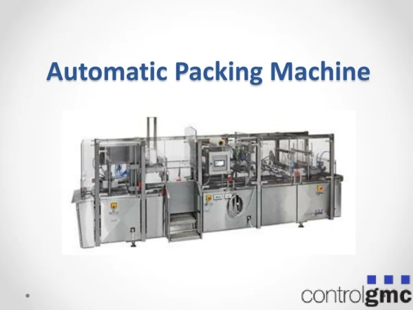
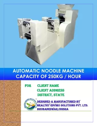
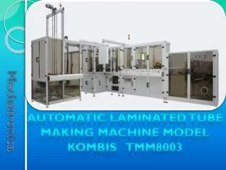
Automatic laminated tube making machine model kombis tmm8003. Unwinding module. Application. Unwinding module is designed for unwinding of laminate tape, for its steering, for the cutting of the necessary width and for the easy feeding of material to body-maker.

E N D
Automatic laminated tube making machine model kombis tmm8003
Application Unwinding module is designed for unwinding of laminate tape, for its steering, for the cutting of the necessary width and for the easy feeding of material to body-maker.
The purpose of the Unscrewing mechanisms is to provide a swift and even unwinding of the foil from the main roll. Like an option the machine is provided with two places for laminate rolls. Its helps prevented when the one finished.
Unwinding module The unwinding module has some basic mechanisms: • Unscrewing roll – one or two (like an option) • Table for foil connection – single or double • Regulating mechanism • Cutting mechanism (Block knives) • Dragging mechanism In the rear of the module: • Electromagnetic brake • Tension regulator (Stretcher I) • Speed regulator (Stretcher II) Other mechanisms: • Nozzle • Sensor agglutination
Unscrewing roll The unscrewing roll is the first mechanism for unwinding the foil. When the rolls are two we have a faster process to change the foil from one to second roll. Two rolls One roll
table for foil connection single or double The table for foil connection serves for facilitating of the sticking of the laminate tapes. The machines with two rolls, the table is hanged on an axle and has two fixed positions. Each position is purposed for one of the two rolls. Two tables One table
TENSION REGULATOR The function of tension regulator- Stretcher I (P1) is to provide constant tension on the foil. The optical sensor mounted on the mechanism used to switch on/off electromagnetic brake.
regulating mechanism The regulating mechanism is designed to lead the edge of the foil incessantly on one and the same spot towards the cutting knives as the size of the tube is strictly defined and in order for a quality welding to be obtained an additional cutting of the foil is needed.
cutting mechanism Knifes block consists of two parts Push-button bushing with retaining knife and knife-holders. Push-button bushing with retaining knife and knife-holderspresents a support construction on which there are attached two knives which may be tuned by the four axles so that a tape with width one millimetre at least to be cut.
dragging mechanism The dragging mechanism is the latest mechanism in the unscrewing module. It’s function is to drag the foil by two bushes, one of witch is with rubber coating. The other bush is driving by motor in the rear of the module.
Speed REGULATOR The Speed regulator – Stretcher II (P 2) is designed to control the speed of foil by Dragging mechanism. The flag with special contour and the Ultrasonic sensor on the rear side allow the foil to move with linear speed in dependent of BODYMAKER’s speed. Flag Rear side Ultrasonic sensor Front side
electromagnetic brake In the rear of the module over the same axle an electrical magnet brake is mounted which guide is implemented by an electricity switch A38/A39, increasing the signal from the optical sensor S06 and the flag to it mounted on the axle of the lever with the stretching roll.
NOZZLE The nozzle for leading away of the foil is situated under the knives and sways the cut thin tapes with the help of air under pressure. The starting and the stopping of the air is implemented with the help of electromagnet valve.
SENSOR AGGLUTINATION The sensor agglutination is mounted above the last roll of Unwinding module. His function is to “see” the scotch tape in the place where the laminate foil is connected. This information is necessary to separate bodies with scotch like bad.
Regulator and manometer for second stretcher CONTROL PANEL • Regulator and manometer for • first stretcher Switch on/off keys for pneumatic cylinders on the first/second connection table Switch on/off keys for pneumatic cylinders on the first/second unscrewing rolls There are two kind of control panels, in depending of number of rolls. Two rolls One roll
All technical details of the described mechanisms can be found in passport “kombis 8003” Or in the www.kombis.net
STEP BY STEP How to start working 2 1 • Step 1: Switch off the key on first unscrewing roll (if you want to work with two rolls do the same with switch key on the second roll) • Step 2: Putt on the roll / rolls (see page 6) • Step 3: Switch on the keys from “Step 1” • Step 4: Check the foil route
Step 5: Drive the foil during the mechanisms: • Connection table (see page 7) • Tension regulator • “Stretcher 1” (see page 8) • Regulating mechanism (see page 9)
Cutting mechanism • You must setup the knifes in dependent of corresponding size (A) • (see page 10) • Dragging mechanism (see page 11) • Speed regulator “Stretcher 2” • (see page 12)
Agglutination sensor (see page 15) • Step 6: Check the manometer on the control panel. The value must be between 1-1,5 bar. (see page 15) • Step 7: Check the keys witch switch on/off pneumatic cylinder on the connection table, if they are on – switch off. ( again see page 15)