Download
1 / 18
200 likes | 629 Vues
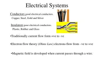
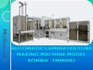
KOMBIS TMM8003 Installation Electrical Systems. Electrical Systems Step Motor Control. Electrical Schematic. This system is used to drive the mechanisms that require accurate positioning . Stepper motors and actuators in the KOMBIS TMM8003 are used for:

E N D
Electrical Systems • Step Motor Control Electrical Schematic This system is used to drive the mechanisms that require accurate positioning. Stepper motors and actuators in the KOMBIS TMM8003 are used for: Foil alignment in the unwinding mechanism and body orientation in the capping station. Power Supply 24 VDC The system includes: EtherCAT Pulse train Up to 2 Input devices Motor lines Pulse train output terminal Driver for stepper motor Stepper motor
Electrical Systems • Step Motor Control Foil Alignment Body Orientation Power Supply 24 VDC Power Supply 24 VDC Orienting the printed design of the bodies is carried out by a stepper motor system before they are loaded onto the mandrels of the rotary table in the capping station. A stepper motor system guides the laminate towards the cutting knives in the unwinding mechanism. Motor lines Pulse train Pulse train Motor lines
Electrical Systems • Asynchronous Motors Control The mechanisms driven by asynchronous motors in the KOMBIS TMM8003 are controlled by frequency inverters. These are specialized devices for controlling induction motors. The inverter changes the speed of the motor while keeping its power constant. With built-in electronic protection it looks after the normal operation of the motor by monitoring overload, overheating, short circuit, phase loss (broken wire), leakage current to the housing of the motor and other electrical process which could damage the asynchronous motor. Motor control – commands include: start, stop, reverse and speed. Diagnostics including inverter status, alarms, etc. are carried out through I/O signals sent between the main controller and the inverter. Circuit breaker Frequency inverter Control with I/O signals or via Interface unit Asynchronous 3- phase motor
Electrical Systems • Asynchronous Motors Control The KOMBIS TMM8003’s frequency inverter system controls asynchronous motors that perform the following movements: Back side view Front side view * Foil unwinding The system is located in the unwinding mechanism and controls foil unwinding (by dragging it) at a speed equal to the speed of the pulling belts in the body maker. It also drives a pulling roll in the friction feed mechanism and the cropping roll of the cutting mechanism. This system is autonomous: using a tension roller and analog sensor fixed to the rollers axis the linear speed of the pulling belts is measured and fed directly to the input of the inverter which controls the rotation of the motor so the foil is pulled at the same speed. Driven rolls Tensioner for speed control Asynchronous motor Inverter
Electrical Systems • Asynchronous Motors Control * Pulling Belts Drive The system is located in the body making mechanism. It is used to drag the laminated foil (wrapped around the beaded mandrel) under the longitudinal seam welding module. This is done by moving transporting belts with a large coefficient of friction (pulling belts), which are pressed to the foil on the mandrel. The foil's speed depends on the linear speed of the transporting belts. The belts are driven via an asynchronous motor controled by the frequency inverter. The commands to start, stop and alter the motor’s speed are initiated by the motion controller through the MECHATROLINK-II interface. Motion Cabinet Body Making Mechanism Pulling belts Inverter with Interface unit Motion controller Gear box Asynchronous motor
Electrical Systems • Asynchronous Motors Control * Transporters drive In the KOMBIS TMM8003 there are two transporters – the first moves the bodies from the body maker to the capping station and the second exports the finished tubes out of the capping station. The drive of both transporters are the same: The conveyor belt is driven by an asynchronous motor and the motor is controlled by a frequency inverter with I/O signals from the main controller. The frequency inverters of both transporters are located in servo drive cabinet. Tubes Transporter Servo Drive Cabinet Body Transporter
Electrical Systems • Servo Motors Control Servo motors in the KOMBIS TMM8003 are powered mechanisms requiring a more dynamic movement and precise positioning. The servo motor system consists of a circuit breaker, servo driver, servo motor and connecting cables. A servo driver can connect to only one servo motor. Speed control, torque control, positioning and the movement ramp of mechanism can be done with either I/O signals from the master controller or a specialized interface from the motion controller. In the second case the servo driver is connected to an interface unit playing the part of "translator" between the motion controller and the servo driver. Circuit breaker : monophase or three-phase OR Servo driver Control with I/O signals Power cable Encoder cable Servo motor
Electrical Systems • Servo Motors Control In the KOMBIS TMM8003 servo motor systems that are controlled by the main controller directly (without any interface units) are:cap winding, cap tightening (final winding) and tube ejection. These systems are located in the capping module. Cap Winding Servo Driver Cabinet Cap Tightening O/I O/I O/I Tube Ejection
Electrical Systems • Servo Motors Control The motion controller in the body maker controls the movements of the servo motor systems used by the flying shearer’s linear guide and cutter along with the capping station’s rotary table, body rotating drum, body load mechanism (onto the mandrels) and the PBL module’s linear guide for shoulder welding. See section Communication and Control. Interface units are mounted to the servo drivers of these systems and are in turn connected by control cables to the MECHATROLINK-II interface of the motion controller. Circuit breaker : monophase or three-phase OR Servo driver + Interface unit Control via Mechatrolink-II interface Power cable Encoder cable Servo motor
Electrical Systems • Vibro-Hoppers Control Shoulders and caps are fed into the KOMBIS TMM8003 by vibrating hoppers. The vibro-hoppers are controlled by I/O signals from the master controller via an intermediate device called the vibrated hopper controller. For normal operation the vibro-hoppers need to work at their resonant frequency. The vibrated hopper controller accomplishes this by using a control algorithm and automatically tunes to the vibro-device. The controller also has a defense function which is duplicated in hardware to guarantee system safety. Vibro-Hopper Circuit breaker Vibrated Hopper Controller O/I ~220V
Electrical Systems • Hot Air Control The hot air system is designed to produce hot air with defined flow and temperature necessary for the welding of plastic (PBL) tubes. The system includes the following devices: Temperature Regulator 3 x ~ 400 V ~ 250 V Circuit breaker three-phase Thermo sensor Control Relays temperature feedback Electronic Relays Hot Air device Work air flow (with integrated electrical heaters) Min. air flow Flowmeter Flow Regulators
Electrical Systems • Hot Air Control Body Maker The body maker’s hot air system is used to weld the longitudinal seam of the bodies when using PBL foil. Welding Module Capping Station PBL-1 Module Control Panel In the capping station this system is used to weld the shoulders of the bodies in the production of PBL tubes. The machine will have a special module installed for shoulder welding called a “PBL-1 Module”. Air Distributer
Electrical Systems THROUBLE SHOOTING
Electrical Systems THROUBLE SHOOTING
Electrical Systems THROUBLE SHOOTING
Electrical Systems THROUBLE SHOOTING
Electrical Systems THROUBLE SHOOTING