Download
1 / 27
270 likes | 388 Vues
Comprehensive guide with circuit diagrams, design data, and troubleshooting tips for Service Engineers working on PAL color transmission systems. Follow step-by-step repair procedures to solve TV issues efficiently and effectively. Points include safety measures, component testing, and use of recommended parts to prevent recurring faults.

E N D
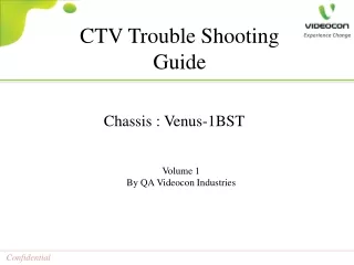
CTV Trouble Shooting Guide Chassis : Venus-1BST Volume 1 By QA Videocon Industries
Chassis : Venus-1BST • Content • Preface • Important tips...……………………………………………………………………..Page 01 • Circuit Diagram………………………………………………………………………….02 • Design Data………………………………………………………………………………03~07 • Applicable models………………………………………………………………………..08 • Set Dead…………………………………………….……….………………..……09 • Set Std. by…………………………………………………………………………..10 • No Sound…..……………………………………….………....................................11 • No Raster………………………………………….………......................................12 • H- Line…………………………………………….……………………..….……...13 • V- Line………………………………………………………………………………14 • No Color ……………………………………………………………………………15 • Snowy Picture / No Tuning /Channel Skipping….………………………………...16 • Plain Raster ………………………………………………………………………...17 • Retrace line…………………………………………………………………………18 • One Color Missing (Red/ Blue/ Green)…………………………………………….19 • AV Mode No Color & No Picture …………………………………………………20 • RF Mode No Color & Intermittent No Color………………………………………21 • Defocus Picture (Ghost Effect) ……………………………………………………22 • Color Patch…………………………………………………………………………23 • Remote Not Operate……..…………………………………………………………24
Chassis : Venus-1BST Preface In this Guide Book, circuit diagram, their associated voltages, Design & Service data, and step by step trouble shooting guidelines are given for Service Engineer reference. Trouble shooting procedure and circuit diagram used in this manual are based on mainly PAL color transmission system. When actually trouble shooting, technician should always refer schematic diagram of defective receiver, and symptom wise step by step repairing tips should be followed to avoid repeat calls and to give one time solution to our customers.
Chassis : Venus-1BST Important Tips • A good repairman conducts a prompt diagnosis of the trouble symptoms and repairs the defective set in the shortest possible time. Do not trouble-shoot a circuit unless you have determined what stage in it is defective. When trouble-shooting a particular stage, always remember its function. This will help you diagnose its operation and find the defective stage and the defective component. • Wear cotton gloves while trouble-shooting, to avoid electrical shock. Also note that, especially in tropical areas, sweat on the hands may later on cause corrosion • Never remove a component from the circuit unless you have confirmed it to be • defective. In some cases, when you suspect a component to be defective, you may find it necessary to disconnect one of its terminals, or the component itself, from the circuit for testing. Before doing this, first measure voltage or observe wave-forms. If a reading is wrong, analyze the circuit and check which component may be causing the trouble and should be tested. • 4. Discharge large capacitors and the stored charge in the cathode-ray tube (CRT) to • avoid dangerous shocks—especially when trouble-shooting the CRT circuits or the • horizontal output circuit. • 5. Always use standard parts recommended by company to avoid repeat failure Page 01 of 24
Chassis : Venus-1BST Double click here for .pdf file Page 02 of 24
Chassis : Venus-1BST Design Data Page 03 of 24
Chassis : Venus-1BST Design Data Page 04 of 24
Chassis : Venus-1BST Design Data Page 05 of 24
Chassis : Venus-1BST Design Data Page 06 of 24
Chassis : Venus-1BST Design Data Page 07 of 24
Chassis : Venus-1BST Applicable models Sansui Videocon Page 08 of 24
Chassis : Venus-1BST Set Dead VOLTAGE CHART STR COQ765RT Pin 1 : 250V Pin 2 : 0 V (GND) Pin 3 : 18.2V Pin 4 : 1.1V Pin 5 : 5 V SMPS Secondary D 815 : +17V D 814 : +15V D816 : +12V D 811 : +110V D 813 : +24V Check AC Socket, Power cord, Power switch, Fuse Replace and check Abnormal Normal Abnormal Check Rectifier diodes, NTC(NT801) Replace diodes /NTC and check Normal Abnormal Check C805, SMPS Check C805, STR Pin 1 Voltages (250V), Normal Abnormal Check D802, VD802, R801, R802 Check 18V at Pin3 of STR Normal Abnormal Check secondary rectifier diodes Replace STR, Check secondary Voltage Normal Check as per STD. BY Guideline Page 09 of 24
Chassis : Venus-1BST Std. by VOLTAGE CHART STR COQ765RT Pin 1 : 250V Pin 2 : 0 V (GND) Pin 3 : 18.2V Pin 4 : 1.1V Pin 5 : 5 V SMPS Secondary D 815 : +17V D 814 : +15V D816 : +12V D 811 : +110V D 813 : +24V Micon Audio Voltages : Pin 3: 8V Pin56 : 0.4V Abnormal Check +B Voltage 110V at D811 cathode Check D811, SMPS, FBT and replace Normal Abnormal H-out Tr. Base 0.5V Check HDT, Driver Tr. V401 Normal Abnormal Replace VD853 & VD852 Check SMPS secondary Voltages, VD853(8.2V) & VD852(5.1V) Abnormal Abnormal Check by disconnecting load Replace SMPS Normal Abnormal Check the section loading supply Check & Replace part Normal Dry pin no.3 & check on track for 8V, check & change crystal X201 If ok then replace micon Abnormal Check Micon Pin no. 3 for 8V Normal Abnormal Check Micon Pin no. 56 (0.4V), Pin no. 38 (3.3V) Replace Micon, V841 Page 10 of 24
Chassis : Venus-1BST No sound VOLTAGE CHART IC 7297 Pin 1 : 8.8V (O/P-1) Pin 2 : 8.8 V (O/P-2) Pin 3 : 17 V (Vcc) Pin 4 : 0.9V Pin 5 : 0.9V Pin 6 : NC Pin 7 : NC Pin 8 : 0.6V Pin 9 : 0V (GND) Pin 10 : 0V Pin 11 : 4.9V Pin 12 : 0.9V Pin 13 : NC Pin 14 : NC Pin 15 : 0.9V Pin 16 : 0.9V Pin 17 : 17V Pin 18 : 8.6V Pin 19 : 8.6 V Micon Audio Voltages : Pin 58,59: 3.57V Pin 31 (UnMute) : 0V Mute : 0.6V) Normal Check AC Voltage across speaker Replace speaker Abnormal Normal Replace Speaker connector Check Voltage at Pin1,2 & 14,15 of IC7297 Abnormal Normal Replace IC7297 Check 17V at Pin3,13 of IC7297 Abnormal Abnormal Check C878, D815, VD1, C601 Replace R886/ C878/D815/VD1/C601 Normal Replace SMPS & check 17V Normal Abnormal Check Voltage at pin 58,59 of Micon (3.57V) Replace Micon Normal Check Voltage at pin 31 of Micon (0V) Replace Micon Page 11 of 24
Chassis : Venus-1BST No Raster VOLTAGE CHART Screen Voltage : 675V Heater Voltage : 6.3 V Not Glowing Check EHT Voltage generation By tester on FBT anode wire Go as per STD. BY Guideline Tester Glowing Abnormal Check Screen Voltage on CRT Base (675V) Adjust screen/Replace FBT Normal Abnormal Check Heater Voltage at W77A in CRT Base (6.3V) Replace W77A, Conn. XP501 Normal CPT Replace Page 12 of 24
Chassis : Venus-1BST H. Line VOLTAGE CHART VERTICAL IC LA78040B Pin 1 : NC Pin 2 : 0.57V Pin 3 : 15.81V Pin 4 : -12.81V Pin 5 : -14.75V Pin 6 : 0.587V Pin 7 : 15.88V Abnormal Check Vertical Yoke Wire Change wire, Solder properly Normal Abnormal Check Voltage at pin 2 (+16.5V), pin 4 (15.3V) of Vertical IC301 Check R403, R427, D404, D402, VD401, VD402 Normal Check Vertical IC301 Voltages Abnormal Abnormal Check Micon IC201 pin 14, 15 Voltage (0.6V) Replace Micon IC201 Normal Replace IC301(LA78040/41) Page 13 of 24
Chassis : Venus-1BST V. Line VOLTAGE CHART FBT Pin 1 : 274.5V AC : 20.37V DC Pin 2(+B) : 0V (GND) AC : 108.5V DC Pin 3(V+) : 41.19V AC : 0V DC Pin 4(v-) : 30.46V AC : 0.13V DC Pin 5(GND) : - - - - Pin 6(Heater) : 7.10V AC : 0V DC Pin 7 : 41.85V AC : 80mV DC Pin 8(ABL) : 2.16V AC : 6.27V DC Pin 9 : - - - - - Pin 10 (180V) : 23.1V AC : 108.5V DC Abnormal Check Yoke Conn. Change wire & check for dry solder Normal Abnormal Check Horizontal yoke continuity Change yoke assembly Normal Abnormal Resolder (L401, burn & track) Check for Dry in L401 (coil) ,burn & track cut. Page 14 of 24
Chassis : Venus-1BST No color DESIGN DATA Sub Colour (SCL) : JCT & Thomson – 60 Samtel – 63 USER DATA Colour Setting – 50 Colour System - PAL Abnormal Check Signal condition (>40dB) Correct signal from Cable operator Normal Abnormal Change colour step to 50 Check color in User mode Normal Abnormal Check color system in User mode Change colour system to PAL Normal Abnormal Change EEPROM & Load Design data Check Sub color in design data (Refer right side Table) Normal Abnormal Check Crystal X201 for dry solder & open Replace crystal and check Normal Micon Change Page 15 of 24
Chassis : Venus-1BST Snowy Picture / No Tuning /Channel Skipping VOLTAGE CHART Tuner Voltage Pin1 : 3.0V ~1.9V(At good signal) Pin2 : 2.39V Pin3 : 0 V Pin4 : 1.8V Pin5 : 2.1V Pin6 : NC Pin7 : 4.99V Pin 8- NC Pin 9 -33.99V Pin 10 –NC Pin 11- DESIGN DATA AGCT Value GDC Tuner : 25 ONIDA Tuner : LONGSIN : Abnormal Check RF cable / Signal strength Replace RF cable, Contact cable operator Normal Abnormal Reduce sharpness by 50% Check sharpness setting in User mode and design data Normal Abnormal Check AGCT Value in Design data(Refer side table) Change AGCT Value As per side table Normal Abnormal Resolder and check Check dry solder in all Tuner pins Normal Abnormal Check all Tuner Pin Voltages Check supply related ckt. Replace tuner Normal Abnormal Replace & Check Check V101 transistor Normal Replace Micon Page 16 of 24
Chassis : Venus-1BST Plain Raster Tuner Voltage Pin1 : 3.0V ~1.9V(At good signal) Pin2 : 2.39V Pin3 : 0 V Pin4 : 1.8V Pin5 : 2.1V Pin6 : NC Pin7 : 4.99V Pin 8- NC Pin 9 -33.99V Pin 10 –NC Pin 11- Abnormal Check tuner voltages C 131 faulty Normal Abnormal Check Micon Pin no. 12 & 13 (VIF in 2V) Replace Micon Normal Abnormal Replace Micon Check V101 Page 17 of 24
Chassis : Venus-1BST Retrace line VOLTAGE CHART IC501 VIDEO IC TDA6107JF Pin 1 : 2.35V DC Pin 2 : 2.35V DC Pin 3 : 2.1V DC Pin 4 : 0V (GND) Pin 5 : 3.8V DC Pin 6 : 182V DC Pin 7 : 162V DC Pin 8 : 155V DC Pin 9 : 159V DC Abnormal Check Screen by adjusting FBT (screen pot) without disturbing the upper pot. Adjust pot or replace FBT Normal Abnormal Check 180V supply on CRT Board ( CN501 Conn) Replace D403 or FBT Normal Check R G B voltage at CN501 R , G , B 1.8V to 2V (Pin no. 44, 45 & 46) Abnormal Replace Micon Normal Check IC501 & VD501~ VD504 R G B voltages (2V) Abnormal Replace IC501/ VD501~VD504 Page 18 of 24
Chassis : Venus-1BST One color Missing ( Red / Blue / Green ) VOLTAGE CHART IC501 VIDEO IC TDA6107JF Pin 1 : 2.35V DC Pin 2 : 2.35V DC Pin 3 : 2.1V DC Pin 4 : 0V (GND) Pin 5 : 3.8V DC Pin 6 : 182V DC Pin 7 : 162V DC Pin 8 : 155V DC Pin 9 : 159V DC Abnormal Check CRT base RGB pin dry solder Touch-up and check Normal Check Video IC IC501 dry solder Abnormal Touch-up and check Normal Check R,G,B i/p on CRT connector XP501 ( 2.2V) Normal Replace Video IC IC501 and check Abnormal Abnormal Check Continuity Connector Xp501 to Xp201 on main PCB Replace and check Normal Abnormal Burning of R285 , R286 , R287 Replace and check Normal Abnormal Check voltage at micon pin 44,45,46 ( 2.1 V) Micon replace and check Page 19 of 24
Chassis : Venus-1BST AV Mode No Color & No Picture Abnormal Check for faulty instrument e.g. DVD, Setup box, AV cable Replace the instrument Normal Abnormal Check AV board for dry or track cut. Touchup & resolder Normal Abnormal Check voltage at C221 at micon Pin no. 62 ( 2V) Replace and check C221 Normal Check AV Socket to C221 track (any track cut present) Normal Abnormal Check Crystal X201 dry solder Replace and check X201 Normal Replace Micon and check Page 20 of 24
Chassis : Venus-1BST RF Mode No color RF Mode Intermittent No color Abnormal Check Color System Auto / Pal Change System to (Auto / Pal) Normal Check pin no. 24 & 25 of micon ( 1.6V ) Replace Tuner and check Normal Abnormal Check Crystal X201 dry solder Replace and check X201 Normal Micon faulty Replace and check Page 21 of 24
Chassis : Venus-1BST Defocus Picture VOLTAGE CHART FBT Pin 1 : 274.5V AC : 20.37V DC Pin 2(+B) : 0V (GND) AC : 108.5V DC Pin 3(V+) : 41.19V AC : 0V DC Pin 4(v-) : 30.46V AC : 0.13V DC Pin 5(GND) : - - - - Pin 6(Heater) : 7.10V AC : 0V DC Pin 7 : 41.85V AC : 80mV DC Pin 8(ABL) : 2.16V AC : 6.27V DC Pin 9 : - - - - - Pin 10 (180V) : 23.1V AC : 108.5V DC FBT (T444) adjust upper (focus pot) without disturbing the lower pot. Normal Check for focus wire fitment & CRT socket. Normal Replace Chassis to confirm CPT or Chassis problem Abnormal If CPT then replace CPT else once again Check the chassis Abnormal -Check FBT -Check for Convergence(Menu Display) -Check for RGB cut-off (in black & white pic.) -Adjust Contrast & Brightness in user mode & if not then in SVC mode. Page 22 of 24
Chassis : Venus-1BST Color Patch • AUTO DEGAUSSING ABILITY CHECKING • Create little patch by External degaussing coil • Switch off the set for 15~20 min. • Switch on set after 20 min. • Check No patch should be there. • If still patch is there open back cover and check D. coil connector • Insert connector properly and check OK Try to remove patch with external degaussing coil. Check Auto Degaussing ability of set Abnormal Check for magnetic device nearby (e.g. external speaker, metal parts, etc.) Abnormal Remove magnetic devices Check for degaussing connector fitment, PTC, D coil , relay & also for dry solder. Replace Part Normal Use CPT magnet strip as mentioned in procedure. Abnormal Abnormal If still not then follow complete procedure for Patch removal. Replace CPT Page 23 of 24
Chassis : Venus-1BST Remote not operate Abnormal Check for panel key stucking & battery(spring contact) Change the battery Normal Abnormal Abnormal Check connector XPC11 Check TV functioning with SVC remote Replace connector Normal Normal Check for remote PCB ckt. else change the remote Check IR sensor RM901A ( Pin-1 : 5V , Pin-2 : GND, Pin-3 : 4~5V) Abnormal Replace RM901A if still not then check voltage at micon pin 39 (4~5v) Abnormal Replace Moicon Page 24 of 24