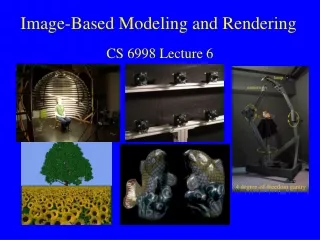
Recent Methods for Image-based Modeling and Rendering
IEEE VR 2003 tutorial 1. Recent Methods for Image-based Modeling and Rendering. Darius Burschka Johns Hopkins University Dana Cobzas University of Alberta Zach Dodds Harvey Mudd College. Greg Hager Johns Hopkins University Martin Jagersand University of Alberta Keith Yerex

Recent Methods for Image-based Modeling and Rendering
E N D
Presentation Transcript
IEEE VR 2003 tutorial 1 Recent Methods forImage-based Modeling and Rendering Darius Burschka Johns Hopkins University Dana Cobzas University of Alberta Zach Dodds Harvey Mudd College Greg Hager Johns Hopkins University Martin Jagersand University of Alberta Keith Yerex Virtual Universe Corporation
IEEE Virtual Reality 2003Next Lectures • Single view geometry and camera calibration. • Multiple view projective, affine and Euclidean Geometry. Scene and object modeling from images. • Differential image variability and dynamic textures. • Real-time visual tracking and video processing. • Hard-ware accelerated image-based rendering. • Software system and hands-on lab.
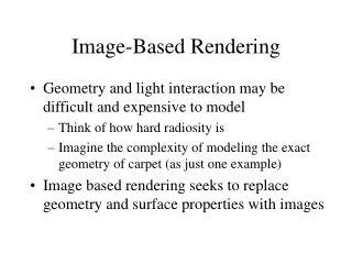
Image-based ModelingRendering IBR/IBM: Label on a wide range of techniques Promising for various reasons, e.g.: • Cameras are cheap/common while 3D laser range sensors are expensive and manual modeling time consuming. • Achieving photo-realism is easier if we start with real photos. • Speed up graphics rendering by warping and blending whole images instead of building them from components in each frame. • Common trait: Images serve important role. Partially or wholly replaces geometry and modeling.
Image-based Models fromconsumer cameras • Rendering of models obtained using a $100 web cam and a home PC (Cobzas, Yerex Jagersand 2002) We’ll learn how to do this in the lab this afternoon…
Photo-Realism from images 1. Geometry+images (Debevec – Camillo Façade) 2. Set of all light rays –Plenoptic function Capture Render new views
Rendering speed-up Post-warping images Blending a light basis
Modeling: Two Complementary Approaches Conventional graphics Image-based modeling and rendering real images geometry, physicscomputer algorithms geometry, physicscomputer algorithms synthetic images synthetic images
Confluence of Computer Graphics and Vision • Traditional computer graphics(image synthesis, forward modeling) • Creating artificial images and videos from scratch • Computer vision & image processing(image analysis & transformation, inverse modeling) • Analyzing photographs & videos of the real world • Both fields rely on the same physical & mathematical principles and a common set of representations • They mainly differ on how these representations are built
Object & Environment Modeling • Basic techniques from the conventional (hand) modeling perspective: • Declarative: write it down (e.g. typical graphics course) • Interactive: sculpt it (Maya, Blender …) • Programmatic: let it grow (L-systems for plants, Fish motion control) • Basic techniques from the image-based perspective: • Collect many pictures of a real object/environment; rely on image analysis to unfold the picture formation process (principled) • Collect one or more pictures of a real object/environment; manipulate them to achieve the desired effect (heuristic)
Rendering • Traditional rendering 1. Input: 3D description of 3D scene & camera 2. Solve light transport through environment 3. Project to camera’s viewpoint 4. Perform ray-tracing • Image-based rendering 1. Collect one or more images of a real scene 2. Warp, morph, or interpolate between these images to obtain new views
Important Issues in Image-BasedModeling and Rendering • What are theoretical limits on the information obtained from one or multiple images? (Geometry) • How to stably and reliably compute properties of the real word from image data? (Comp Vision) • How to efficiently represent image-based objects and merge multiple objects into new scenes? (CG) • How to efficiently render new views and animate motion in scenes? (IBR)
Information obtained from images • Viewing geometry describes global properties of the scene structure and camera motion • Traditional Euclidean geometry • Past decade surge in applying non-Euclidean (projective, affine) geometry to describe camera imaging • Differential properties in the intensity image gives clues to local shape and motion. • Shape from shading, texture, small motion
Viewing Geometry andCamera Models Viewing Geometry Euclidean Calibrated camera Affine “Infinite” camera Projective Uncalibrated cam Scene object C C C sim aff proj R t A t { g | g GL(4), g = , A GL(3) } { g | g GL(4), g = , R SO(3) } 0 1 0 1 Visual equivalent Shape invariant transform { g | g GL(4) } Possibly ambigous shape!
Intensity-based Information • We get information only when there is intesity difference (Baker et.al. 2003) • Hence there are often local ambiguities
Photo-Consistent Hull • In cases of structural ambiguity it is possible to define a photo-consistent shape – “visual hull” (Kutulakos and Seitz 2001)
Two main representations inImage-Based Modeling Ray set = Plenoptic function Geometry and texture (X,Y,Z) Represents … “the intensity of light rays passing through the camera center at every location, at every possible viewing angle (5D)”
Image Mosaics • When images sample a planar surface or are taken from the same point of view, they are related by a linear projective transformation (homography). • So … images can be mosaicked into a larger image • 3D plenoptic function. m=[u,v]T m’=[u’,v’]T (u,v) (u’,v’)
Cylindrical Panorama Mosaics • Quicktime VR: Warps from cylindrical panorama to create new planar view (from same viewpoint)
Image and View Morphig Generate intermediate views by image/ view/ flow-field interpolation. • Can produce geometrically incorrect images
Image and View Morphing - Examples Beier &Neely – “Feature-Based Image Metamorphosis“ • Image processing technique used as an animation tool for metamorphosis from one image to another. • Specify correspondence between source and destination using a set of line segments pairs.
View Morphing along a line • Generate new views that represent a physically-correct transition between two reference images. (Seitz & Dyer)
Light Field Rendering Sample a 4D plenoptic function if the scene can be constrained to a bounding box Approximate the resampling process by interpolating the 4D function from nearest samples. (Levoy & Hanrahan)
The Lumigraph Gortler and al.; Microsoft Lumigraph is reconstructed by a linear sum of the product between a basis function and the value at each grid point (u,v,s,t). acquisition stage volumetric model novel view
Concentric Mosaics H-Y Shum, L-W He; Microsoft Sample a 3D plenoptic function when camera motion is restricted to planar concentric circles.
Pixel Reprojection Using Scene Geometry Images Renderings • Geometric constranits: • Depth, disparity • Epipolar constraint • Trilinear tensor Laveau and Faugeras: Use a collection of images (reference views) and the disparities between images to compute a novel view using a raytracing process.
Plenoptic Modeling McMillan and Bishop: Plenoptic modeling (5D plenoptic function): compute new views from cylindrical panoramic images.
Virtualized Reality T. Kanade -CMU • 49 cameras for images and six uniformly spaced microphones for sound • 3D reconstruction: volumetric method called Shape from Silhouette
Layer Depth Images Shade and al. LDI is a view of the scene from a single input camera view, but with multiple pixels along each line of sight. movie
Relief Textures Augment 2D texture map with depth map Render new views by 3D Pre-warp onto poly Perspective warp into cam • Oliviera 00
Image-based Objects Envelope object with coarse geometry Map textures+depth through 3D warp from each polygon Texture 2D texturing 3D texturing
Rendering Architecture from Photographs Combine both image-based and geometry based techniques.“Façade” (Debevec et. al.)
Structure from motion poses Tracked features structure Structure from motion algorithm Estimated geometry at best approximation of true
Geometric re-projectionerrors dynamic static Texturing:
Spatial Basis Intro (Jagersand 1997) • Moving sine wave can be modeled: • Small image motion Spatially fixed basis 2 basis vectors 6 basis vectors
Geometric SFM and dynamic textures Training Model New view I1 It Structure P New pose (R a b) … = = (R1 a1 b1) …(Rt at bt) Motion params + + Texture basis (Cobzas, Yerex Jagersand 2002) Warped texture y1 … yt Texture coeff
Geometric SFM and dynamic texturesExample Renderings • Rendering of models obtained using a $100 web cam and a home PC (Cobzas, Yerex Jagersand 2002) We’ll learn how to do this in the lab this afternoon…
IEEE Virtual Reality 2003Next Lectures • Single view geometry and camera calibration. • Multiple view projective, affine and Euclidean Geometry. Scene and object modeling from images. • Differential image variability and dynamic textures. • Real-time visual tracking and video processing. • Hard-ware accelerated image-based rendering. • Software system and hands-on lab.