Download
1 / 25
340 likes | 772 Vues
Design of an LC-VCO with One Octave Tuning Range. Andreas Kämpe and Håkan Olsson. Radio Electronics-LECS/IMIT Royal Institute of Technology (KTH). VCO research has largely focused on reducing phase noise, not tuning range.

E N D
Design of an LC-VCO with One Octave Tuning Range Andreas Kämpe and Håkan Olsson Radio Electronics-LECS/IMIT Royal Institute of Technology (KTH)
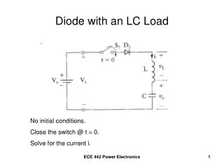
VCO research has largely focused on reducing phase noise, nottuning range. Multi standard transceivers requires wideband VCOs with low phase noise Goal: Designing a VCO with one octave tuning range while maintaining a low phase noise and low power consumption. Introduction
VCO topologies • LC tank • + Low phase-noise. • + Low power consumption • Large chip area • Tuning range (limited by CMAX/CMIN). Delay element Ring, transmission line, and relaxation oscillators + Small chip area - High phase noise and realativly high power consumption.
VCO Architecture • Complementary structure (N & P) MOS => • larger amplitude and symetric rise/fall time => • Reduced power / phase noise
LC-tank and wide tuning range • One octave tuning range => • Requires a Capacitance tuning of 2 octaves. • Tuning capacitor Cmax / Cmin > 4 (paracitcs: CP) • Low voltage and large Cmax/Cmin => High varactor sensitivity (VCO gain) => sensitive to noise on the control line.
Discrete tuning CMOS technology offers excellent switches. Bandswitching The switched capacitors are used as band selectors (coarse tuning) Channel selection is performed digitally. + Increased tuning range + Reduces the varactor gain => phase noise reduction.
Switch limitations (MOSFET) • Low capacitive load Large tuning range • Minimum loss Low power consumption
Trade-off Lossorcapacitive load. Minimum loss = reduce Rds-on = wide transistor with minimum gate length. Minimum capacitive load = reduce Cgs /Cgd =narrow transistor with minimum gate length.
Switch Optimisation • NMOS transistors (higher transconductance). • Drain / source are AC coupled (band sw cap) and biased via resistors => maximizes (Vgs-Vt) • =>Reduced Rds-on
Switch On Switchon: Vgs = 1.8V => Minimum RDS
Switch Off Switchoff:Vgs = -1.8 V=> 20% reduction in capacitance compared to having Drain and Source biased at 0 V.
Capacitor array 3bits binary weighted Capacitor array.
Varactor • Accumulation-mode mos varactors => • Less steep voltage to capacitancetransfer. • 4 varactors are conected anti parallell => • Differential operation and control => • Common mode rejection
Inductor • + Differential inductor (increased coupling). • +3 metal layers (M6, M5, M4) are stacked on top of each other => reduces the series resistance. => increased Q • - Increased capacitive load (Lower metal layers are closer to the substrate).
Inductor simulations Optimized and designed with ASITIC and ADS.
Inductor model • Lumped model of a transmission line.
Inductor-model simulations Lumped model error ”Real(S)”.
Inductor-model simulations • Lumped model error ”Imag(S)”.
Amplitude Variations • The oscillation amplitude varies considerably across the wide tuning range Requires an adjustable negative resistance => Achieved by controlling the biasing current.
VCO The band selection also controlles the biasing current. => Constant oscillation amplitude over the entire tuning range.
Tuning range Large tunability 1.2 GHz – 2.6 GHz.
VCO’s * Quadrature VCO
Conclusions • It is possible for a VCO to have a large tuning range combined with a low phase noise and low power consumption. This design has a very good performance expressed in FOM (-190 dBc/Hz/mW) and superior if the wide tuning range is taken in account. • Large chip Area, due to many capacitors and a large inductor. If the oscillator was designed to be operated at a higer frequency, the Chip area could be decreced (smaller LC tank) The down side is an increaced loss in the switches (capacitor array).
Complementary or NMOS-only 1 • ID(n + p) = ID(n-only) • Equal gm: gm(n + p) = gm(n-only)
Complementary or NMOS-only 2 • Symetric rise/fall time: