Download
1 / 124
1.26k likes | 1.76k Vues
Learn about air-break circuit breakers, their construction principles, and applications in medium and low voltage switchgear. Understand the design components and operation of miniature circuit breakers.

E N D
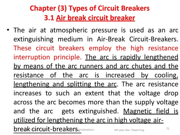
Chapter (3) Types of CircuitBreakers • 3.1 Air break circuitbreaker • The air at atmospheric pressure is used as an arc extinguishing medium in Air-Break Circuit-Breakers. These circuit breakers employ the high resistance interruption principle.The arc is rapidly lengthened by means of the arc runners and arc chutes and the resistance of the arc is increased by cooling, lengthening and splitting the arc. The arc resistance increases to such an extent that the voltage drop across the arc becomes more than the supply voltage and the arc getsextinguished. Magnetic field is utilized for lengthening the arc in high voltageair- breProaf.Dkr.ScayeidrAc.Wuaridt-breakeC.Brsasnd.Substations 72 4th year elec. PowerEng.
Air-break circuit breakers are used in d..c. circuit and a.c. circuits up to12KV. • The air-break circuit breakers are generally indoor type and installed on vertical panelsor indoor draw-out typeswitchgear. • A.C. air circuit breaker are widely used in indoor medium voltageand low voltageswitchgear. • Typicalreferencevaluesofratingsofair-break circuit breaker are: • 460 V , 400-3500 A, 40-75KA • 3.3 KV , 400-3500 A, 13.1-31.5KA • 6.6 KV , 400-2400 A, 13.1-20KA • Prof. Dr. SayedA.Ward C.Bsand Substations 4th year elec. PowerEng. 73
3.1.1 Construction of Air-breakCircuit-breaker • In the air-break circuit-breaker the contact separation and arc extinction takes place in air at atmospheric pressure. As the contacts are opened, arc is drawn between them. Thearc core is a surrounding cooling the conducting medium arc, the 'path'of contains plasma.The By ionized air. diameterofarccoreis reduced. The arc is extinguished by lengthening the arc, cooling the arc and splitting the arc. The arc resistance is increased to such an extent that thesystemvoltagecannotmaintainthearcand the arc getextinguished. Prof. Dr. SayedA.Ward C.Bs andSubstations 74 4th year elec. PowerEng.
Figure4illustratesthenormalarrangementof an air break circuitbreaker. • This type of breaker is used for medium and lowvoltages. 75 Prof. Dr. Sayed A.Ward C.Bs andSubstations 4th year elec. PowerEng.
An air circuit breaker for low voltage (less than 1000 volts) power distributionswitchgear 76 Prof. Dr. SayedA.Ward C.Bsand Substations 4th year elec. PowerEng.
77 Prof. Dr. Sayed A.Ward C.Bs andSubstations 4th year elec. PowerEng.
The 10 ampere DINrail-mounted thermal-magnetic miniature circuit breaker is the most common style in modern domestic consumerunitsand commercial electrical distributionboards throughout Europe. The design includes the followingcomponents: Actuatorlever- used to manually trip and reset the circuit breaker. Also indicates the status of the circuit breaker (On orOff/tripped). Actuator mechanism - forces the contacts together or apart. 3.Contacts - Allow currentwhentouchingandbreakthe current when moved apart. 4.Terminals 5.Bimetallicstrip. Calibrationscrew- allows themanufacturerto precisely adjustthe trip current of the device afterassembly. Solenoid Arc divider/extinguisher 78 Prof. Dr. SayedA.Ward C.Bsand Substations 4th year elec. PowerEng.
There are two sets of contacts : Main contacts (1) and Arcing contacts (2). Main contacts conduct the current in closed position of the breaker. They have low contact resistance and are silver plated. The arcing contacts (2) are hard, heat resistance and are usually of copper alloy. While opening the contacts, the main contacts dislodge first. The current is shifted to the arcing contacts. The arcing contacts dislodge later and arc is drawn between them (3). This arc is forced upwards by the electromagnetic forces and thermal action. The arc ends travel along the arc Runners (Arcing horns). The arc moves upwards and is split by arc splitter plates (arc chutes) (5) as shown by the arrow (4). The arcextinguished by lengthening, cooling, splitting etc. In some breakers the arcisdrawninthedirectionofthesplitterbymagnetic fielPdro.f. Dr.SayedA.Ward 79 C.Bsand Substations 4th year elec. PowerEng.
Furthermore, air-break circuit-breaker have been developed with current limiting feature, magnetic blow-up of arc,etc. • Air break a.c. circuit breakers are widely used forindustrialswitchgear,auxiliaryswitchgearin generation employing station. lengthening Air break ofarc,arc principle runners, magnetic blow-ups breaker up to 15KV. areusedfor d.c.circuit 80 Prof. Dr. Sayed A.Ward C.Bs andSubstations 4th year elec. PowerEng.
5.1.2 Miniature and Molded-Case CircuitBreaker • These are used extensively in low voltage domestic, commercial and industrial applications. They replace conventional fuses and combine the features of a good HRC fuse and a good switch. Figure 5 gives the internal details of a thermal magnetic miniature circuit breaker.For normal operation, it is used as a switch. During over loads or faults, it automatically trips off.The tripping mechanism is actuated by magnetic (part 7) and thermalsensingdevices(part5)providewithinthe MVB. 81 Prof. Dr. Sayed A.Ward C.Bs andSubstations 4th year elec. PowerEng.
Figure5 The internal details of a 10 ampere European DIN railmounted thermal-magnetic circuitbreaker Prof. Dr. SayedA.Ward C.Bsand Substations 4th year elec. PowerEng. 82
Figure contents: Actuator lever - used to manually trip and reset the circuit breaker. Also indicates the status of the circuit breaker (On or Off /tripped). Most breakers are designed so they can still trip even if the lever is held or locked in the On position. This is sometimes referred to as "free trip" or "position trip" operation. Actuator mechanism - forces the contacts together orapart. contacts - Allow current to flow when touching and break the flow of current when movedapart. Terminals Bimetallicstrip calibration screw - Allows the manufacture to preciselyadjust the trip current of the device afterassembly. Solenoid 8. ArcPdrofi. vDr.iSdayeedrA./WaerdxtinguishCe.Bds andSubstations 83 4th year elec. PowerEng.
Typical Rating of MCB: Current Rating : 5, 10, 15, 20, 30, 40, 50, 60Amp. also, 0.5, 0.75, 1, 2, 2.5, 3, 3.5, 6, 7.5, 8, 10,12, 25, 35, 45, 55Amp. Voltage Rating : 240 V/415 V AC; 50 V/11 V DC RupturingCapacity: AC: 3 KA at 415V DC: 3 KA at 50 V ( non-inductive), 1 KA at 110 V(non-inductive). 84 Prof. Dr. Sayed A.Ward C.Bs andSubstations 4th year elec. PowerEng.
5. 2. Air-BlastCircuit-Breaker • 5.2.1Introduction • Air blast circuit breakers are used today from 11 to 1100 KV, for various application. They offer several advantages such as faster operations, suitability for related operation, auto-reclosure, unit type multi- breakconstruction, simple, assembly, modest maintenance, etc. A compressor plant is necessary to maintain high air pressure in the receiver. Air- blast circuit breakers operates repeatedly. Air-blast circuit breakers are used for interconnectedlines andimportant desired. Prof. Dr. Sayed A.Ward lineswhenrapidoperationis C.Bsand Substations 4th year elec. PowerEng. 85
5.2.2 Constructionof Air-BlastCircuit-Breaker • In air blast circuit breaker (also called compressed air circuit breaker) high pressure air is forced on the arc through a nozzle at the instant of contact separation. The ionized medium between the contacts is blown away by the blast of the air. After the arc extinction the chamber is filled with high pressure air, which prevents restrike. In some low capacity circuit breakers, the isolator is an integral part of the circuit breaker. The circuit breaker opens and immediately after that the isolator opens, to provide additiongap. • In EHV circuit of today, isolators aregenerally indePprof.eDrn.SadyedeA.nWatrdlymounCt.BesanddSu(bFstaitigons.6). 86 4th year elec. PowerEng.
( a )Principle C.Bs andSubstations 87 Prof. Dr. Sayed A.Ward 4th year elec. PowerEng.
( b ) Schematicconstruction Prof. Dr.FSaiyegdAu.Wraerd6 Air blaC.BssatndcSuibrstcatiuonsit break4tehyreariesleoc.PloawetroEnrg.connec88tion
Figure 7 shows one pole of the EHV airblastcircuitbreaker.Inthe completeassemblythere identical arethree poles. 89 Prof. Dr. Sayed A.Ward C.Bs andSubstations 4th year elec. PowerEng.
90 Prof. Dr. SayedA.Ward C.Bs andSubstations 4th year elec. PowerEng. Figure 7 One pole of an extra high voltage air blast circuitbreaker
Description: High pressure air between 20 to kgf/cm2 , is is stored in the air reservoir (item 1 in Fig. 7). Air is taken from compressed air system. Three hollow insulator columns (item 2) are mounted on the resrvoir with valves (6) at their base. The double arc extinguishing chambers (3) are mounted on the top of the hollow insulator chambers. The current carrying parts (7) connect the three arc extinction chambers to each other in series and the pole to theneighbouring equipment.sincethereexistaveryhighvoltage between the conductor and the airreservoir, the entirearcextinctionchamberassemblyis 91 mouPronf.Dtr.eSaydedAo.Wnard insulatCo.BsransdS.ubstations 4th year elec. PowerEng.
The detailsof the double arc extinction chambers (3) are shown in Fig. 8. Since there three double arc extinction poles in series, thereare six breakers per pole. Each arc extinction chamber (Fig. 8) consists of one twin fixed contact. There are two moving contacts which are shown in the closing process. The moving contacts can move axially so as to open or close. Its position open or close depends on air pressure and spring pressure. 92 Prof. Dr. Sayed A.Ward C.Bs andSubstations 4th year elec. PowerEng.
Figure8 Extra high voltage air blast circuitbreaker 93 Prof. Dr. Sayed A.Ward C.Bs andSubstations 4th year elec. PowerEng.
The operation mechanism (item 4 in Fig. 7) operates the rods (item 5) when it gets a pneumatic or electrical signal. The valves (6) open so as to send the high pressure air in the hollow of the insulator. The high pressure air rapidly enters the double arc extinction chamber. As the air enters into the arc extinction chamber the pressure on the moving contacts becomes more than spring pressure and contacts open. • The contacts travel through a short distance against the spring pressure. At the end of contacts travel the part for outgoing air is closed by the moving contacts and the entire arc extinction chamber is filled with high pressure air, as the air is not allowed to go out. However, during the arcing period the air goes out through the openings and takes away the ionized air ofarc. 94 Prof. Dr. SayedA.Ward C.Bs andSubstations 4th year elec. PowerEng.
• While closing, the valve (6) is turned so as to close connection between the hollow of the insulator and the reservoir. The valve lets the air from the hollow insulator to the atmosphere. As a result the pressure of air in the arc extinction chamber (3) is dropped down to the atmospheric pressure and the moving contacts close over the fixed contacts by virtue of the spring pressure. the opening is fast because the air takes a negligible time to travel from the reservoir to the moving contact. The arc is extinguished within acycle. Therefore, air blast circuit breaker is very fastin breaking thecurrent. Prof. Dr. SayedA.Ward C.Bs andSubstations 95 4th year elec. PowerEng.
Closingis also fast because thepressure inthearc extinctionchamberdropsimmediatelyasthevalue (6) operates and the contacts close by virtue of the spring pressure. • Theconstruction describedbelowappliesto air-blast above circuit-breakersforEHVapplications,forvoltages • 145 KV. For voltages of 420 KV and more, the construction is modified by adding required number of arc interrupting chambers inseries. • Air blast circuit breaker requires an auxiliary compressed air system. • Air blast circuit breakers for 12 KV are generally having a different type of construction. Air blast circuit breakers are preferred for furnace duty and traction system arenot satisPfraof.cDrt.SoayerdyA.WfaordrsuchdCu.BtsainedSsu.bstations 96 4th year elec. PowerEng.
Typical rating of AirBlastCircuit Breaker are: • 12 KV, 40KA • 22 KV,40KA • 145 KV, 40 KA, 3cycles • 245 KV, 40 KA, 50 KA, 2.5cycles • 420 KV, 40 KA, 50 KA, 63.5 KA, 2cycles • The grading capacitors are connected across the interrupter unit for the equal distribution of voltage between the units. closing resistors (Fig. 9) are connected across the interrupter units for limiting the over voltages during closing operation. Opening resistors are connected across the interrupterunits tomProaf.Dkr.eSayetdAh.WeardcircuitCb.BsranedSaubkstaetionrssrestr4tihkyeearelfecr.PeoweerE.ng. 97
Figure9 Configuration of switchingresistor 98 Prof. Dr. SayedA.Ward C.Bsand Substations 4th year elec. PowerEng.
5.2.3 Principle of ArcQuenching • in Air Blast CircuitBreaker • The air blast circuit breaker needs an auxiliary compressed air system which supplies air to the air receiver of the breaker. For opening operation, the air is admitted in the arc extinction chamber. It pushes away the moving contacts againstspring pressure. In doing so, the contacts are separated and the air blast takes away the ionized gases along with it and assists arc extinction. After few cycles the arc is extinguished by the air blast and the arc extinction chamber is filled with high pressure air (30kgf/cm2 ). The high pressure air has higher dielectric strength than that of atmospheric pressure. Hence a small contact gap of a few centimetre isenough. 99 Prof. Dr. SayedA.Ward C.Bsand Substations 4th year elec. PowerEng.
The flow of air around contacts is guided by the nozzle shaped contacts. It may be axial, across or a suitable combination { Fig. 10(a),(b)}. 100 Prof. Dr. Sayed A.Ward C.Bs andSubstations 4th year elec. PowerEng.
101 Prof. Dr. Sayed A.Ward C.Bs andSubstations 4th year elec. PowerEng.
Figure10 Flow of air around contacts in air blast circuitbreaker 102 Prof. Dr. SayedA.Ward C.Bsand Substations 4th year elec. PowerEng.
In the axial blast type air flow Fig. 10 (a) the flow air is longitudinal, along the arc. In axial blast type air flow, the air flows from high pressure reservoir to the atmospheric pressure through a convergent divergent nozzle.The difference in pressure and the design of nozzle is such that as the air expands into the low pressure zone, it attains almost supersonic velocity. The mass flow of air through the nozzle is governed by the parameters like pressureratio, area of throat, nozzle throat diameter and is influenced by the diameter of the arcitself. 103 Prof. Dr. Sayed A.Ward C.Bs andSubstations 4th year elec. PowerEng.
The air flowing at high speed axially along the arc causes removal of heat from the periphery of the arc and the diameter of the arc reduces to a low value at current zero. At this instant the arc is interrupted and the contact space is flushed with fresh air flowing through thenozzle. • The flow of fresh air through the contact space ensures removal of hot gases and rapid building up of the dielectric strePronf. Drg.SatyedhA.W.ard 104 C.Bsand Substations 4th year elec. PowerEng.
The principle of cross blast illustrated in Fig. 10 (b) is used only in the circuit breaker of relatively low rating such as 12 KV, 500MVA. • The experience has shown that in the cross blast flow,the air flows around the arc and the diameter of arc is likely to remain stable for higher values ofcurrent. • Duringtheperiodofarcextinction,theair • continues to flow through the nozzle to the atmosphere. The mass flow rate can be increased by increasing the pressure system. the increase in the mass flow results in increased breakingcapacity. 105 Prof. Dr. Sayed A.Ward C.Bs andSubstations 4th year elec. PowerEng.
After the brief duration of air flow, the interrupter is filled with high pressure air. The dielectric strength of air increases with pressure. Hence the fresh high pressureair in the contact space is capable of withstanding the transient recoveryvoltage. • After the arc extinction the interrupter chamber is filled with high pressure air. For closing operation, the air from this chamber is let out to the atmosphere. Thereby the pressure on the moving contacts from one side is reduced and the moving contacts close rapidly by the spring pressure (Fig. 11). 106 Prof. Dr. Sayed A.Ward C.Bs andSubstations 4th year elec. PowerEng.
Figure 11 Principle of Operation inABCB 107 Prof. Dr. Sayed A.Ward C.Bs andSubstations 4th year elec. PowerEng.
5.2.4 Merits and Demerits of AirBlast CircuitBreaker • Merits : • Can be used at highpressure. • Reliable operation due to external source of extinguishing energy. • Free fromdecomposition. • Clean,non-inflammable. • Air is freely availableeverywhere. • Fresh medium is used every time. Hence the breaker can be repeatedly operated, if designed for suchduty. • At high pressure the small contact travel isenough. • Thesameareservespurposeofmovingthecontactand108arc • Prof. Dr. SayedA.Ward C.Bsand Substations 4th year elec. PowerEng.
High speed of operation. The compressed air moves very fast and brings about the opening operation. The arcing time is also short. Hence totalbreaking time is short operationmechanism of air blast circuit breaker are pneumatic.Thearcingtimeisalmostexactly0.01second, • i.e 1/2 cycle plus another 1/2 cycle for operation the contacts. Hence breaker speed of the order of 2 cycles can be achieved. This makes the circuit breaker suitable for important lines because high speed opening and auto- reclosure can improve systemstability. • Rapid auto-reclosure The circuit breaker can be given rapid auto-reclosure feature. The manufacturer gives such a provision at additional cost. The ABCB is easy to reclose because the reclosure is by spring pressure againstreduced airpressure. Prof. Dr. Sayed A.Ward 109 C.Bs andSubstations 4th year elec. PowerEng.
Clean service. No need of maintenance as ofoil • Unit type construction gives advantage in design, manufacturer andtesting • Very high breaking capacities and service voltage can be obtained by connection more number of units in series. Hence for all extra high voltage and high breaking capacities of today air-blast circuit breakers are used, e.g. 420 KV, 63.5 KA, 2cycles • Suitability for repeated operation, The fresh air is used every time. Hence the breaker can be used for repeated operation if designed for duty. This is not the case with oil circuitbreaker. 110 Prof. Dr. Sayed A.Ward C.Bs andSubstations 4th year elec. PowerEng.
Demerits: • Complex design of arc extinction chambers and operating mechanisms, problems for switching over voltages are reduced by reclosingresistors. • Auxiliary high pressure air system is necessary. The cost can be justified if there several breakers in the switching yard. For a single breakers the cost of auxiliary compressed air system would be toohigh. 111 Prof. Dr. Sayed A.Ward C.Bs andSubstations 4th year elec. PowerEng.
5.2.5 Maintenanceaspects • Maintenance of ABCB is comparatively easier than that of tank type oil circuit breaker and minimum oil circuit breaker. This is because there is no oil, which needs regular testing and purefication. Secondly, the units can be easily deassembled, checked and reassembled. The assembly of various units is similar and easy. The operating mechanism can be easily dismantled andreassembled. • The major problem in air blast installation is the leakage from compressed air system and from the pipe connection. The leakage takes place from the threaded joints or from mating parts joined bymeans ofnPurotf.D-r.bSayoedlAt.Wsard 112 C.Bsand Substations 4th year elec. PowerEng.
5.3 Bulk Oil and MinimumOil CircuitBreaker • Suchcircuitbreakersutilizedielectricoil (transformeroil)forarcextinction.Inbulkoil circuit breakers, the contacts are insideasteelfilledwithdielectric separated oil.In minimum oil circuit breakers, the contacts are separated in an insulation housing (interrupter)filled with dielectricoil. • 113 Prof. Dr. Sayed A.Ward C.Bs andSubstations 4th year elec. PowerEng.
The oil in oil circuit breakers( OCBs) serves two purpose. It insulates between the phases and between the phases and the ground, and it provides the medium for the extinguishing of the arc. When electric arc is drawn under oil, the arc vaporizes the oil and creates a large bubble that surroundthe arc. The gas inside the bubble is around80% hydrogen, which impairs ionization. The decomposition of oil into gas requires energy that comes from the heat generated by the arc. The oil surrounding the bubble conducts the heat away from the arc and thus also contributes to deionization of thearc. 114 Prof. Dr. SayedA.Ward C.Bsand Substations 4th year elec. PowerEng.
Main disadvantage oftheoilcircuitbreakersisthe • flammability of the oil, and the maintenance necessary to keep the oil in good condition ) i.e. changing and purifying theoil). • Bulkoilcircuitbreaker(tanktypecircuitbreakers)are becoming obsolete and have been described here inbrief. • Minimum oil circuit breaker has the following demerits: • 1. Shortcontactlife. 2. frequentmaintenance. • Possibility of explosion. • Larger arcing time for smallcurrent. • Prone tore-strike • They are being superseded by SF6 circuit breakers inall ranPgroef.Dsr..SayedA.Ward 115 C.Bsand Substations 4th year elec. PowerEng.
5.3.1 Tank type or Bulk Oil Circuit Breaker (now obsolete) • Bulk oil circuit breakers are enclosed in metal-grounded weatherproof tanks that are referred to as dead tanks. The tank type circuit breakers had 3 separate tanks for 72.5 KV and above (Fig. 12a). For 36 KV and below, single tank construction, phase barriers were provided betweenphase. • The contact separation takes place in steel tanks filled with oil. The gases formed, due to the heat of the arc, expand and set the turbulent flow in the oil. The arc was drawn directly inside of the container tank without any additional arc extinguishing but the one provided by the gas bubble surrounding the arc. Plain break breakers were superseded by arc controlled oilbreakers. 116 Prof. Dr. SayedA.Ward C.Bsand Substations 4th year elec. PowerEng.
To assist arc extinction process, arc control devices were fitted to the contact assembly. These were semi-enclosed chamber of dielectric materials.The purpose of the arc control devices is to improve operating capacity, speed up the extinction of arc, and decrease pressure on the tank.The performance of oil circuit breaker depended on the effectiveness of the arc controldevices. 117 Prof. Dr. Sayed A.Ward C.Bs andSubstations 4th year elec. PowerEng.
Prof. Dr.SayedA.W(arda)115CK.BsaVndSubcstaitironcs uitbr4ethayekareelecr.PowerEng. 118
( b) 66 KV circuitbreaker TypeC.sBsanodSufbstbatiounslkoil4cthiyeracreluec.PiotwebrEnrg.eaker119 FPirogf.Dur.SaryeedA.W1ar2d
The breakers incorporate arc control are called arc control circuitbreakers. • These are two types of suchbreakers: • Self blast oil circuit breakers - in which arc control is provided by internal means i.e. are itself facilitates its own extinctionefficiency. • Forced blast oil circuit breakers - in which arc control is provided by mechanical means external to the circuitbreaker. 120 Prof. Dr. SayedA.Ward C.Bsand Substations 4th year elec. PowerEng.
Self blast oil circuit breaker– • in this type of breakers, the gases produced during arching are confined to a small volume by the use of an insulating rigid pressure chamber or explosion pot surrounding the contacts. The space available for the arc gases is restricted by the chamber so a very high pressure is developed to force the oil and gas through or around the arc to extinguish it. The magnitude of the pressure depends upon the value of fault current to be interrupted. The arc itself generates the pressure so such breakers are also called self generated pressure oil circuitbreakers. 121 Prof. Dr. Sayed A.Ward C.Bs andSubstations 4th year elec. PowerEng.