Download
1 / 33
340 likes | 517 Vues
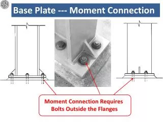
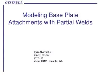
Modeling Base Plate Attachments with Partial Welds. Rob Abernathy CASE Center GTSUG June, 2012 Seattle, WA. What is a “Partially Welded Attachment”?.

E N D
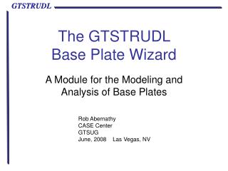
Modeling Base Plate Attachments with Partial Welds Rob Abernathy CASE Center GTSUG June, 2012 Seattle, WA
What is a “Partially Welded Attachment”? Attachments are assumed to be welded to the base plate along all attachment lines. However, in some situations, only part of the attachment is welded to the base plate. In versions 31 and earlier of the Base Plate Wizard, this situation could only be modeled by creating a custom attachment which included the welded parts of the attachment and omitted the unwelded parts. Version 32 adds new tools to allow modeling the unwelded parts of attachments. GTSUG June, 2012
Custom Attachment Omitting Unwelded Lines A wide flange welded on the flanges but not the web could be modeled as 2 lines, leaving out the line representing the web. You would need to create the two line version since the standard profiles are assumed to be welded all around. Custom W8x10 - Flanges only Standard W8x10 GTSUG June, 2012
Custom Attachment .gtbp Files From Appendix A1 The GTBP File Format 100 ID type Profile_ID OffsetX OffsetY RotX RotY RotZ Extension 110 Profile_ID Shape Mirrowed Name Table values[6] int Profile_ID: Matches with Profile_ID in Attachment (100) int Shape: 1: I, 2: tube, 3: channel, 4: T, 5: 2L, 6: L, 100: Arbitrary 120 Profile_ID type X1 Y1 X2 Y2 CX CY THICK $ ---- Attachments: Standard W8X10 --------------- 100 1 0 1 0.0000 0.0000 0.0000 0.0000 0.0000 0.0000 110 1 1 0 W8X10 WSHAPES9 7.8900 3.9400 0.1700 0.2050 0.0000 0.0000 $ ---- Attachments: Custom W8X10 --------------- 100 1 0 1 0.0000 0.0000 0.0000 0.0000 0.0000 0.0000 110 1 100 0 W8x10-Flanges Custom 7.8900 3.9400 0.0000 0.0000 0.0000 0.0000 120 1 0 -1.9700 3.8425 1.9700 3.8425 0.0000 0.0000 0.2050 120 1 0 -1.9700 -3.8425 1.9700 -3.8425 0.0000 0.0000 0.2050 GTSUG June, 2012
Issues with Omitted Lines • Omitting attachment lines that are not welded introduces two concerns. They may or may not affect your results – engineering judgment must be exercised. • Issue 1: If an unwelded and therefore un-modeled part of the attachment were to translate in the –Z direction (into the base plate) or the base plate were to deflect in +Z direction in an area where an omitted line was would cause an inconsistency between the physical structure and the mathematical model. • Issue 2: An “extension” model could not be created for the un-modeled part of the attachment, effectively precluding using this method for unwelded portions of the attachment. GTSUG June, 2012
How to Model Unwelded Attachment Sections? The edge of a plate butted against but not welded to a base plate should transfer compressive force to the base plate, but not tension or shear (ignoring friction) forces and no moments. This condition will be referred to as “Contact Only”. Two components in GTSTRUDL can model this type of action: Nonlinear Spring (NLS) elements and TYPE SPACE TRUSS members declared as COMPRESSION ONLY with the NONLINEAR EFFECTS command. GTSUG June, 2012
Modeling Contact Only with NLS Nonlinear springs are already used to model the compression-only bearing surface, in much the same way as is needed for Contact Only, exerting only +Z force without shear. However, NLS elements add more complexity, requiring curve data and element stiffness assignments like the bearing surface NLS: NONLINEAR SPRING PROPERTIES CURVE 'BearSurf' FORCE 0.0 0.0 -3907664.702093 -10.0 END OF NONLINEAR SPRING PROPERTIES NONLINEAR SPRING ELEMENTS INCIDENCES 'S1‘ ATTACHED TO JOINT 1 STIFFNESS 'S1' Z CURVE 'BearSurf' FACTOR 0.06250 END OF SPRING DATA GTSUG June, 2012
Modeling Contact Only with Compression Only • TYPE SPACE TRUSS members designated as COMPRESSION ONLY with the NONLINEAR EFFECTS command will also transfer only +Z resistance without shear or moments. For several reasons, compression only members was decided as the modeling method: • Simple, easy to understand commands • 2. Able to be viewed in GTMenu • 3. Less complicated internal nonlinear processing GTSUG June, 2012
Stiffness Connection between Contact Only Attachment and Base Plate Both the compression-only and NLS methods need a spring constant to represent the resistance to compression between the Contact Only attachment and the base plate. This resistance can be viewed as the transverse compression of the base plate due to the –Z force applied by the Contact Only attachment. A spring constant equal to a short, stubby steel member was chosen to model the transverse stiffness of the base plate. GTSUG June, 2012
Implementing Contact Only in the Base Plate Wizard A Contact Only designation has been added to attachment lines, along with a line’s start and end location and its thickness. Because any part of an attachment may be Contact Only, any attachment with Contact Only will make that attachment ‘Arbitrary’, instead of wide flange, channel, etc. More on Arbitrary vs. standard profiles later. GTSUG June, 2012
Contact Only Modeling Rules #1 and #2 #1 - If a joint is part of both welded and unwelded lines, it is considered to be welded. Note: this should only occur at line ends. #2 - Base plate joints along a Contact Only line have new joints created ½ plate thickness above (+Z) them, corresponding to the top of the plate. $ ---- Base Plate Wizard user defined data ---------------------- $ Plate: 4.000 in X 6.000 in x 0.5000 in Thickness = 0.5 $ ---- CONTACT ONLY joints and connecting members ---- JOINT COORDINATES 36 1.723 1.637 0.250; 37 1.723 3.000 0.250; 38 3.319 1.637 0.250 GTSUG June, 2012
Contact Only Modeling Rules #3 and #4 #3 - Compression-only members (TYPE SPACE TRUSS) are added between the plate joints and the new Contact Only joints. #4 - AX equal to MeshSize*MeshSize is assigned to the new members. TYPE SPACE TRUSS MEMBER INCIDENCES 25 36 13; 26 37 18; 27 38 14 MEMBER PROPERTIES AX 1.000000 25 TO 27 NONLINEAR EFFECTS COMPRESSION ONLY MEMBERS 25 TO 27 GTSUG June, 2012
Contact Only Modeling Rules #5 and #6 #5 - If the attachment is modeled as a Rigid Footprint, then the RIGID SOLID includes the new Contact Only joints, but not the plate joints. #6 - If the attachment is modeled as 2D finite elements (extension), then the first row of the extension elements are incident to the new Contact Only joints, not the plate joints. GTSUG June, 2012
Simple Example Create an 8” x 10” plate with a W8X10 centered, with a 1” mesh. Generate a .gtbp file and an input file and run it. View in GTMenu, noting the RIGID BODY display. Edit the attachment and set the web as Contact Only (unwelded). Generate a .gtbp file and an input file and run it. View in GTMenu, noting the RIGID BODY display. Compare the two .gtbp files. GTSUG June, 2012
Simple Example: Generate files Save the fully welded standard profile into Simple.gtbp and then create an input file Simple.gti. Check the “Process Input File” box to be able to view the model in GTMenu. GTSUG June, 2012
Simple Example: View in GTMenu GTSUG June, 2012
Simple Example: Set Web as Contact Only On the Attachment page, edit the attachment by double-clicking the column, then click the ‘Edit Weld Status’ button. GTSUG June, 2012
Simple Example: Select Web and Change Status Note that the web is marked as line 1. Click the “1” in the Line # column. Line 1 becomes dashed, indicating it’s selected. In the Tools menu, select “Set selected lines as Contact Only. Line 1 returns to a solid line, but is now rose colored, indicating that the web is now considered Contact Only. Click the OK button to accept the new weld status. GTSUG June, 2012
Simple Example: Accept Contact Only Change When you return to the Edit Attachment dialog, the web line will still be blue. Click the OK button at the bottom of the dialog to commit the new weld status. GTSUG June, 2012
Simple Example: Generate Contact Only Files When a standard profile has Contact Only lines, it must be stored as an Arbitrary profile. This dialog informs you of that and also offers two renaming options. Click the NO button (reject the suggested new name) to bring up the New Attachment Name dialog. You can select from the existing tables or type in a new name. Type in a new profile name. 39 character limit for both names. GTSUG June, 2012
Simple Example: View Contact Only in GTMenu Note the web is now modeled as a row of joints above the mid-plate joints. These new joints are ½ plate thickness in the +Z direction and the RIGID SOLID includes the new joints and not the plate joints. GTSUG June, 2012
Simple Example: Geometry Close-up Only Z force (which is FX for the members) is carried by the truss members (81 and 82 in this picture) and only a compressive force. If joints 100 and 23 move away from each other, the member 81 transmits no force. $ ---- CONTACT ONLY joints and connecting members ---- JOINT COORDINATES 100 4.000 2.000 0.250; 101 4.000 3.000 0.250; TYPE SPACE TRUSS MEMBER INCIDENCES 81 100 23; 82 101 32; MEMBER PROPERTIES AX 1.000000 81 TO 87 NONLINEAR EFFECTS COMPRESSION ONLY MEMBERS 81 TO 87 GTSUG June, 2012
Simple Example: Compare .gtbp Files Simple.gtbp $ ---- Attachments: 1 attachments specified --------------- 100 1 0 1 0.0000 0.0000 0.0000 0.0000 0.0000 0.0000 110 1 1 0 W8X10WSHAPES9 7.8900 3.9400 0.1700 0.2050 0.0000 0.0000 SimpleContactOnly.gtbp $ ---- Attachments: 1 attachments specified --------------- 100 1 0 1 0.0000 0.0000 0.0000 0.0000 0.0000 0.0000 110 1 100 0 W8x10-FlangesPartiallyWelded 7.8900 3.9400 0.0 0.0 0.0 0.0 120 1 4 0.0000 -3.8425 0.0000 3.8425 0.0000 0.0000 0.1700 120 1 0 -1.9700 3.8425 0.0000 3.8425 0.0000 0.0000 0.2050 120 1 0 0.0000 3.8425 1.9700 3.8425 0.0000 0.0000 0.2050 120 1 0 -1.9700 -3.8425 0.0000 -3.8425 0.0000 0.0000 0.2050 120 1 0 0.0000 -3.8425 1.9700 -3.8425 0.0000 0.0000 0.2050 Attachment type ( 1 = W shape, 100 = Arbitrary) Profile Table name Line type (0 = welded, 4 = Contact Only) GTSUG June, 2012
Example 2: Partially Welded Channel Compare results from a fully welded channel (C8x11.5) with results from two partially welded channels welded with the patterns shown. Pattern 1 Pattern 2 GTSUG June, 2012
Example 2: Plate with Anchors and Loads Loads are applied at the end of 10” 2D extension, creating MX (loads Down and UP) and MY (loads Left and Right). GTSUG June, 2012
Example 2: Create Custom Attachment Since the weld patterns do not match the standard profile lines (flanges and web), a custom attachment is required with the line definition matching the weld pattern. The custom attachment below (MyChannels::C8x11.5-Parts2x4) breaks the flanges into 2 parts and the web into 4 parts. 110 1 100 0 C8x11.5-Parts2x4 MyChannels 8.0000 2.2600 0.0 0.0 0.0 0.0 120 1 0 -0.4610 -3.8050 -0.4610 -1.9025 0.0000 0.0000 0.2200 120 1 0 -0.4610 -1.9025 -0.4610 0.0000 0.0000 0.0000 0.2200 120 1 0 -0.4610 0.0000 -0.4610 1.9025 0.0000 0.0000 0.2200 120 1 0 -0.4610 1.9025 -0.4610 3.8050 0.0000 0.0000 0.2200 120 1 0 -0.4610 3.8050 0.6690 3.8050 0.0000 0.0000 0.3900 120 1 0 0.6690 3.8050 1.7990 3.8050 0.0000 0.0000 0.3900 120 1 0 -0.4610 -3.8050 0.6690 -3.8050 0.0000 0.0000 0.3900 120 1 0 0.6690 -3.8050 1.7990 -3.8050 0.0000 0.0000 0.3900 GTSUG June, 2012
Example 2: View Custom Attachment This is the view you would see in Edit Weld Status. Create separate .gtbp files for each pattern. Then write and run the .gti files and compare the ResultsSummary files. GTSUG June, 2012
Example 2: Results Comparison All WeldedPattern 1Pattern 2 Von Mises 15675 18658 31578 S1 17580 19951 35413 S2 -18089 -20309 -34347 B1 612 607 614 B2 701 703 646 GTSUG June, 2012
Attachments in .gtbp and the Attachment File The .gtbp and Attachment File formats are described in Appendices A1 and A2 of the Base Plate Wizard User Guide. In addition, examples of custom attachments are shown in the file ‘SampleUserDefinedAttachments.txt’ in the <install>\GTStrudl\xx\BasePlate folder (“<install>” = C:\Program Files (x86) or your alternative location, and “xx” = the version number). Custom attachments built on a standard profile are simple, as we have seen. The next slide shows the standard profile lines – if they match your welds it is simple to create a partially welded attachment file. GTSUG June, 2012
Standard Profile Lines This the line layout with line numbers for the standard profiles from the GTSTRUDL AISC 9th Edition tables. The Edit Weld Status dialog easily lets you change the status of any individual line to Contact Only. If only part of a line is Contact Only, then you will need to create a custom Attachment File. GTSUG June, 2012
Custom Attachments in the Attachment File $ In the .gtbp file 110 1 100 0 C8x11.5-Pattern2 MyChannels 8.0000 2.2600 0.0 0.0 0.0 0.0 120 1 0 -0.4610 -3.8050 -0.4610 -1.9025 0.0000 0.0000 0.2200 120 1 4 -0.4610 -1.9025 -0.4610 0.0000 0.0000 0.0000 0.2200 120 1 4 -0.4610 0.0000 -0.4610 1.9025 0.0000 0.0000 0.2200 120 1 0 -0.4610 1.9025 -0.4610 3.8050 0.0000 0.0000 0.2200 $ In the AttachmentFile TABLE 'MyChannels' $ Name NumberOfLines 100 C8x11.5-Pattern2 8 $ X1 Y1 X2 Y2 THICK Type $ ------- ------- ------- ------- --------- ---- -0.4610 -3.8050 -0.4610 -1.9025 0.2200 -0.4610 -1.9025 -0.4610 0.0000 0.2200 4 -0.4610 0.0000 -0.4610 1.9025 0.2200 4 -0.4610 1.9025 -0.4610 3.8050 0.2200 GTSUG June, 2012
Export Anchor Results for Capacity Anchor Check The new ANCHOR commands in GTSTRUDL 32 need the anchor geometry and results to check anchor capacity by Appendix D of the ACI code. The ability to extract this data has been added to the Anchor Results dialog. Click the Write ANCHOR LOADS button to create a file with the geometry (optional) and results in the format required by the ANCHOR CONFIGURATION command. GTSUG June, 2012
Generated ANCHOR CONFIGURATION Commands ANCHOR 1 X 1.000 Y 1.000 TYPE 'Anchor1' ANCHOR 2 X 9.000 Y 1.000 ANCHOR 3 X 1.000 Y 9.000 ANCHOR 4 X 9.000 Y 9.000 LOAD 'Down' 1 VX 113.9 VY 257.7 TENSION 34.7 2 VX -99.7 VY 243.8 TENSION 22.2 3 VX -119.1 VY 256.5 TENSION 506.0 4 VX 104.9 VY 241.9 TENSION 631.2 END LOAD DATA LOAD 'Up' 1 VX -119.1 VY -256.5 TENSION 506.0 2 VX 104.9 VY -241.9 TENSION 631.2 3 VX 113.9 VY -257.7 TENSION 34.7 4 VX -99.7 VY -243.8 TENSION 22.2 END LOAD DATA GTSUG June, 2012