A Single-Path Pulsewidth Control Loop With a Built-In Delay-Locked Loop
A Single-Path Pulsewidth Control Loop With a Built-In Delay-Locked Loop. Sung-Rung Han , Student Member , IEEE , and Shen-Iuan Liu , Senior Member , IEEE J. Solid-State Circuit , vol . 40 , no . 5 , May 2005. 指導教授 : 林志明 教授 學 生 : 劉彥均. 積體電路設計研究所. Outline. Introduction

A Single-Path Pulsewidth Control Loop With a Built-In Delay-Locked Loop
E N D
Presentation Transcript
A Single-Path Pulsewidth Control Loop With a Built-In Delay-Locked Loop Sung-Rung Han , Student Member , IEEE , and Shen-Iuan Liu , Senior Member , IEEE J. Solid-State Circuit , vol . 40 , no . 5 , May 2005 指導教授:林志明 教授 學 生:劉彥均 積體電路設計研究所
Outline • Introduction • Proposed Architecture • Experimental Results • Conclusion • Reference
Introduction • Power consumption, EMI(electromagnetic interference), coupling effect. • half-rate, double-sampling, 50% duty cycle. • PVT, deviate.
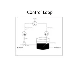
Introduction Conventional PWCL.
Introduction • Problems of conventional PWCL: 1. Phase cannot align. 2. A reference clock with 50% is need. 3. Current mismatch. 4. Large ripple.
Introduction Fixed-phase PWCL
Introduction Mutual-correlated PWCL
Proposed Architecture Proposed Architecture
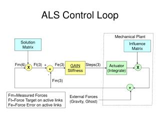
Proposed Architecture Proposed control stage.
Proposed Architecture (a) Phase detector with the start-up circuit. (b) Timing diagram.
Experimental Results Measured reference and output clocks of 1.25 GHz.
Experimental Results Measured jitter for the output clock of 1.25 GHz.
Experimental Results Die photograph
Experimental Results Output waveforms of 1.25 GHz with different duty cycles.
Experimental Results Measured duty cycle errors.
Conclusion • Duty cycle be assured. • Phase alignment. • Reduce duty cycle error. • Duty cycle be adjusted for application.
Reference [1] F. Mu and C. Svensson, “Pulsewidth control loop in high-speed CMOS clock buffers,” IEEE J. Solid-State Circuits, vol. 35, no. 2, pp. 134–141, Feb. 2000. [2] P. H. Yang and J. S. Wang, “Low-voltage pulsewidth control loops for SOC applications,” IEEE J. Solid-State Circuits, vol. 37, no. 10, pp. 1348–1351, Oct. 2002. [3] W. M. Lin and H. Y. Huang, “A low-jitter mutual-correlated pulsewidth control loop circuit,” in Proc. IEEE Int. Conf. Systems-on-Chip, 2003, pp. 301–304.