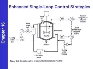
Temperature Control Loop
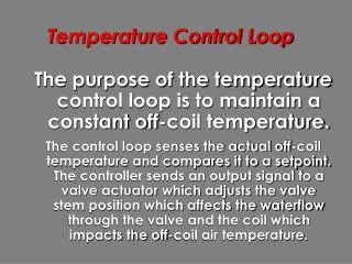
Temperature Control Loop. The purpose of the temperature control loop is to maintain a constant off-coil temperature.

Temperature Control Loop
E N D
Presentation Transcript
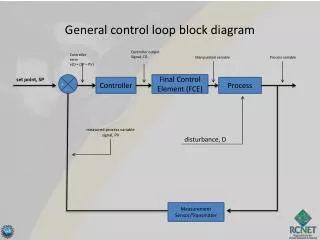
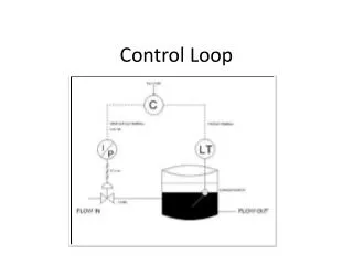
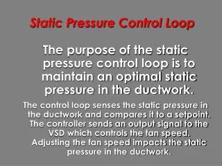
Temperature Control Loop • The purpose of the temperature control loop is to maintain a constant off-coil temperature. • The control loop senses the actual off-coil temperature and compares it to a setpoint. The controller sends an output signal to a valve actuator which adjusts the valve stem position which affects the waterflow through the valve and the coil which impacts the off-coil air temperature.
Temperature Control Loop Off-Coil Temperature DDC Control Calculations Signal to Valve Actuator Position of Valve Stem Water flow through valve / coil
Temperature Control Loop Cooling Coil Off-coil Air Temperature Sensor Air Flow Valve Actuator CHWS CHWR Setpoint and other Tuning Parameters DDC Controller
Temperature Control Loop Control Loop Setpoint
Temperature Control Loop • Control Loop Setpoint • Setpoint of control loop is fixed by building engineer. Choosing too high of a setpoint will result in: • lower chiller energy • higher fan energy • reduced system capacity • higher RH in space
Temperature Control Loop • Control Loop Setpoint • Too low a setpoint may cause the loop to saturate meaning no control. • Common practice is to fix off-coil temperature setpoint between10°C and 14°C.
Temperature Control Loop Chilled Water Valves
Temperature Control Loop • Chilled Water Valves • The chilled water valve should be mounted in the chilled water supply pipe. • If the chilled water valve is in the return valve, then when the valve is closed the coil is full of cold water and condensation will result increasing maintenance problems.
Temperature Control Loop Normally Open Cage Trim Globe Valve Body Packing nut Packing guide Packings Bonnet (Centerpiece) Stem Disk (Integral w/Plug) Plug Cage (Integral Seat) Body
Temperature Control Loop Normally Open Flanged Globe Valve Body • Stem Packing nut Packing guide Packings Packing box Centerpiece Disk holder Disk Plug Seat (screwed in) Plug guide Body
Temperature Control Loop Resilient Seat Butterfly Valve Body Stem Bushing, Stem Seal Stem Retaining Ring Valve System Neck Body Valve Seat Disc
% Flow Quick Opening Linear Equal Percentage Temperature Control Loop Valve Plug Design 100 75 50 25 0 0 25 50 75 100 Quick Opening % Valve Stem Lift Linear Equal Percentage
Temperature Control Loop • Use quick opening plug for two position applications. • Linear plug is typically used for industrial applications. • Equal percentage plug typically used for HVAC applications. Why?
Temperature Control Loop Valve Characteristic + Coil Characteristic = % Flow % Design Capacity 100 100 75 75 50 50 25 25 0 0 0 25 50 75 100 0 25 50 75 100 % Valve Stem Lift % Design Flowrate
% Design Capacity 100 75 50 25 0 0 25 50 75 100 % Valve Stem Lift Temperature Control Loop A roughly linear system characteristic
Uncontrollableflow Temperature Control Loop • All valves experience uncontrollable flow when almost closed.
Temperature Control Loop • Rangeability • A high rangeability means good control under low load conditions. There are different standards to define “Minimum Controllable Flow”
Temperature Control Loop • Cavitation • As water goes through the restricted area between the plug and the seat, the velocity increases and static pressure decreases. If the static pressure drops below the vapour pressure, air bubbles form. After passing the restriction, velocity decreases and static pressure increases. As the static pressure rises, the bubbles implode causing shock waves which result in pitting on the inside of the valve.
Temperature Control Loop • Cavitation Plug to Seat Clearance * * * Flow Implosions Velocity Liquid Vapour Pressure Pressure Pressure Velocity
Temperature Control Loop • Valve Authority Cooling Coil Pv Pt
Temperature Control Loop • Valve Sizing • Undersized valves cannot deliver sufficient flow for maximum load conditions. • Oversized valves must operate at the end of their stroke making tuning more difficult.
Temperature Control Loop • Valve Sizing • For 2 position valves, select the valve according to line size. • For modulating valves, use the design pressure drop and flow rate to calculate the flow coefficient.
Temperature Control Loop • Valve Sizing • Flow Coefficient (Cv) is the USGPM of 60°F water that will flow through a fully open valve with a 1 psi drop across it.
Temperature Control Loop • Valve Sizing Cv = Valve flow coefficient Q = Flow in USGPM Pv = Pressure difference between inlet and outlet in psi
Temperature Control Loop • Valve Sizing Example Q = 90 USGPM Pv = 5 psi (typical) Cv = 90/2.24 = 40
Temperature Control Loop • Valve Sizing • Valves are only manufactured with specific flow coefficients. • After calculating the desired flow coefficient, select the valve with the next lowest coefficient. • Most systems are oversized so slightly undersizing the valve will not compromize system performance, but it does improve system controllability.
Temperature Control Loop Three Way Mixing Valve Body Normally Closed Common Normally Open
Temperature Control Loop • Three Way Valves Pump Cooling Coil C S N.C. Three way valve in mixing application piped N.C. to coil N.O. R Cooling Coil N.C. R C Three way valve in bypass application piped N.C. to coil N.O. S
Temperature Control Loop • Three Way Valves • Three way valves are used for constant flow systems. Constant flow systems are not popular because they waste pump energy. Constant Flow to Building Variable Flow to Building
Temperature Control Loop • Valve Actuator • There are two criticalissues when selectingthe valve actuator: • Close off pressure • Spring return • End switch
Temperature Control Loop • Valve Actuator • For a two way valve, the close off pressure must be sufficient to overcome the pump head. • For a three way valve, the close off pressure is twice the pressure drop across the valve plus the pressure drop across the coil. • If spring return in provided, the valve will return to a known position if the control signal is removed or during a power failure.
Temperature Control Loop Temperature Sensors
Temperature Control Loop • Temperature Sensors An averaging temperaturesensor is mounted inductwork in front of coolingcoil to measure off-coiltemperature.
Temperature Control Loop • Temperature Sensors • Resistance Temperature Detectors (RTD) measure temperature using the resistance property of metals such as nickel or platinum. • The resistance of a thin wire varies linearly over a limited temperature range. Low current is used to avoid self-heating.
Temperature Control Loop • Temperature Sensors • Different metals have different sensitivity to heat. Thermal sensitivity is measured in ohms/ohm/Deg C. • For example, a sensor with a sensitivity of 0.003 ohms/ohm/Deg C and a base resistance of 22°C will change from 1003to 1006as the temperature varies from 23°C to 24°C.
Temperature Control Loop • Temperature Sensors • Two common metals used for RTD areNickel and Platinum. • Both type of sensors are available witha base resistance of 1000Platinum sensors are also available with a base resistance of 100 • Base resistance is not as important as sensitivity and linearity.
Temperature Control Loop • Temperature Sensors • Nickel sensors have a high sensitivity(.00343 C). • Nickel sensors have a slight non-linearityat extreme temperatures and software correction may be required underthese conditions. • Nickel sensors are low cost and can beused for point or averaging elements.
Temperature Control Loop • Temperature Sensors • Platinum sensors have a low sensitivity(.00214 C). • Platinum sensors are very linear for therange of temperatures found in HVAC applications. • Platinum sensors are higher cost and arenot available as averaging elements.
Temperature Control Loop • Temperature Sensors Point Element : Appropriatefor Return Air Temperatureor Room Temperature(well mixed air) Averaging Element : Usedfor Off-Coil Temperature orSupply Air Temperature(turbulent/stratified air)
Temperature Control Loop • Temperature Sensors • Calibrate a temperate sensor by: • Disconnect RTD element. • Replace RTD element with a precision 1000 resistor. • Adjust offset in DDC Controller to read base temperature (this compensates for resistance of wiring). • Replace RTD element.