Download
1 / 35
350 likes | 510 Vues
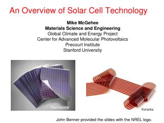
Limiting factors in solar cell efficiency - how do they apply on the nano-scale ?. D.G. Ast Cornell University. From Macro to Nano. 3-D “nano” cell (dye or QM sensitized) record = 12.6% (Graetzel, wet). 1-D “nano” cell (depleted collection) record = 13% (triple - UniSolar).

E N D
Limiting factors in solar cell efficiency - how do they apply on the nano-scale ? D.G. Ast Cornell University
From Macro to Nano 3-D “nano” cell (dye or QM sensitized) record= 12.6% (Graetzel, wet) 1-D “nano” cell (depleted collection) record = 13% (triple - UniSolar) Giant Single Molecule Cell (bulk collection) record =24. 7 %
THE DEVICE VIEW = Jsc Voc FF Jsc Voc
BAND GAP Black body: Thermal emission from cell via above bandgap photons.
Jsc AM 1.5 Theoretical Upper Limit versus bandgap .
Jsc 1. Incident energy flux reduction Reflection (Si ~ 10%) Contact shading Insufficient absorption ( d < )
Jsc 2. Failure to generate electron hole pairs Sub bandgap photons (excluding two photon processes*) Bulk free carrier absorption, “Auger” Free carrier absorption due to V across cell Frank Keldysh effect * investigated in Si for two photon processes
Jsc 3. Failure of e-h to contribute to current Bulk recombination (impurities, structural defects, ) Surface recombination Non-contacted surface Contacted surface
Jsc 4. Remedies Bulk Losses: Clean Starting Materials Gettering Thin bulk ! => Light trapping design ! Collecting from fully depleted layers with uniform (!) electric fields. (No “hang through” !)
Jsc Surface Recombination a. Non contacted area Small Area ! (Implication for “nano” !) Factors influencing S: Capture cross section of surface states (in Si >>for electrons than holes) Hole and electron concentration at surface (Voutput dependent as cminority increases with Vout) Charge of passivating layer
Jsc Contact Areas: Small area ! (Nano, again ) Heavy doping => “ Back surface field” (Graetzel Patents on TiO2)
1. “ Junction Leakage “ Voc Small ni , Long lifetimes (Diffusion distance)
Voc Green , semi-empirical Kiss & Rehwald (thermodynamic) Good a:Si-H (Roca, Meillaud et al.)
Voc Additional contribution(s) to Jo 1. Generation current due to bulk “midgap” states 2. Generation current to due surface states. Sum over exponentials commonly expressed as n, diode ideality factor, function of operating conditions.
2. Junction Defects (shorts, partial shorts, more general: Spatial inhomogeneity) 1. Scale with junction area (nano !) 2. Difficult to diagnose 3. The bane of the multicrystalline cell
FF Empirical relation (Green) Additional Effects Series Resistance : Contacts & Leads Parallel Resistance : Shunts !
Module Efficiency CdTe modules are much less efficient than CdTe cells ! Cells must be uniform ! Cost Not just materials but processing (CIS) Stability a-Si:H, DSC ..
GIANT SINGLE MOLECULE DEVICE PERL cell = 24 % PERL => Passivated Emitter, Rear contact Locally diffused
1-D “NANO” 100 nm 200 nm A-Si:H M. Schmidt, A. Schoepke, O. Milch, Th. Lussky, W. Fuhs N(E) as d
Si reappears via M. Green A(luminum) Induced C(rystallization) I(on) A(ssisted) D(eposition) poly-Si cell (M.Green) 9…12% (Pinnacle of optical engineering)
3-D NANO QM dots
NANO CELLS: Insufficient absorption => Multiple stacking large surface area => junction leakage increased lead length => resistance, recombination Contact shading => transparent electrodes e.g.TiO2surface recombination, parasitic resistance, E drops ! nmismatch => multiple bounce
QD dots sensitized Higher absorption than dyes. More corrosion resistant. Layer 3 is the insulator (TiO2) between organic p conductor and layer 2, the F doped SnO contact layer. Potential large area problem.
Jsc Absorption tuning by PbS QD growth
Jsc Monochromatic Light max ~ 10% Jsc at QD size below optimal optimum. Trade off between coverage (1x), QM size tuning, and transport loss.
Summary Challenges: Transition from single giant molecule cell to nano cell 1. Large increase in junction area .. junction defects. 2. Surface states 2. Transparent conductors…. bandgap matching. 3. Large contact area … shunts Rewards : 1. Bandgap tuning 2. Easier implementation of “sub bandgap” and “hot carrier” . . . ; .. Conversion. 3. Large area for “in situ” chemical conversion !