Download
1 / 12
170 likes | 597 Vues
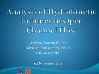
Analysis of Hydrokinetic Turbines in Open Channel Flow. Arshiya Hoseyni Chime Advisor: Professor Phil Malte UW –NNMREC 04 November 2012. Irrigation Canals. Traditional: Sluice gates for flow control Opportunity: Hydrokinetic turbines for flow control and power generation.

E N D
Analysis of Hydrokinetic Turbines in Open Channel Flow Arshiya Hoseyni Chime Advisor: Professor Phil Malte UW –NNMREC 04 November 2012
Irrigation Canals • Traditional: Sluice gates for flow control • Opportunity: Hydrokinetic turbines for flow control and power generation Approximately 1 MW power loss
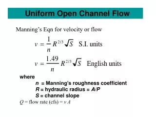
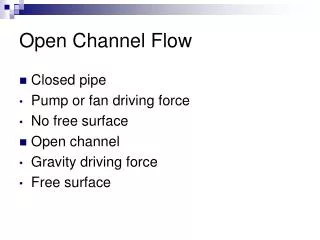
Approach • 1-D modeling using conservation of mass, linear momentum and energy equations • 3-D CFD modeling • Volume of Fluid model • Open Channel Flow Boundary Conditions • Turbines • Actuator Disc Model • Virtual Blade Model • Power generation vs flow control
1-D Theory Turbine Drawing courtesy of Dr. Polagye
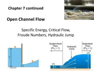
Effect of Channel Constriction on Water Depth Decrease in channel width to increase blockage ratio and velocity Subcritical and supercritical solutions
Effect of Channel Constriction on Power Generation Stream Conditions Flow rate= 130 m3/s Upstream energy=5.08 m 3 Turbines, each with 4 m diameter Froude number=0.18-0.24
CFD-Actuator Disc Model • Fluent14.0 • Volume of Fluid Model • Coupled Pseudo-Transient Solver • turbulence model • Porous Media Model to define resistance across the turbine (DP based on 1D theory) • No slip at walls
Boundary Conditions • Mass flow inlet • Pressure outlet air 2.5 m water 50 kg/s 5 m 132,800 kg/s D=4 m t= 0.2 m 2.5 m 30 m 60 m
Free Surface Elevation Both 1D theory and 3D CFD show a 2% drop in water depth for the 21m case, and a 4% drop for the 16 m case.
Velocity and Dynamic Pressure Profiles (16m) Velocity Magnitude [m/s] Dynamic Pressure [Pa]
To do … • Supercritical Cases with ADM • Virtual Blade Model in Fluent
Acknowledgement • Professor Malte • Professor Riley • Dr. Novosselov • Ms. Megan Karalus • Northwest National Marine Renewable Energy Center • Department of Energy