Download
1 / 26
310 likes | 577 Vues
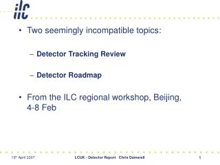
Mechanical Risks to Tracking Detector Bond Wires. Outline. Brief intro to wire bonding Physical contact damage Vibration and shock from transport and handling Damage from thermal cycling and shock Resonant vibration in strong magnetic field Preferred solution: encapsulation.

E N D
Mechanical Risks to Tracking Detector Bond Wires Outline • Brief intro to wire bonding • Physical contact damage • Vibration and shock from transport and handling • Damage from thermal cycling and shock • Resonant vibration in strong magnetic field • Preferred solution: encapsulation A. Honma, CERN PH/DT Thanks to Bond Lab / QART Lab team: Adam Drozd, FlorentinaManolescu, Ian McGill Tracking Detector Mechanics Forum
Brief Intro to Wire Bonding Why a talk on wire bonding for a mechanics forum ? Wire bonding is an industry standard interconnect technology which is used extensively in silicon tracking detectors (between sensors, read-out chips, PCB substrate). The fragile nature of these connections (when unpackaged) make it important for all those that may be involved in the construction of these detectors to understand the relevant risk issues. Historical perspective Wire bonding is an “old” technology used in nearly all packaged IC chips. Connects bare Si die to other die or to package circuit. Uses technology called “thermosonic gold ball bonding”. But, almost no risk since wires are encapsulated in ceramic/plastic package. Tracking Detector Mechanics Forum
Brief Intro to Wire Bonding However, for technical reasons such as the need for fine pitch and the absence of high temperatures, a slightly different wire bonding technology is used almost exclusively for unpackaged HEP wire bonding applications:ultrasonic aluminium wedge bonding. In this case the exposed bond wires are easily damaged. Presentation at 2011 Workshop on Quality Issues in Current and Future Silicon Detectors 2003 Bond Workshop at CERN: http://ssd-rd.web.cern.ch/ssd-rd/bond/default.htm CERN Bondlab: http://bondlab-qa.web.cern.ch/bondlab-qa/Bondlab_Home.html chip/sensor substrate (PCB, ceramic, silicon) Some terminology: loop 1st (source) bond foot 2nd (destination) bond foot heel bond pad Some bonding reference links: Tracking Detector Mechanics Forum
Brief Intro to Wire Bonding Why not “package” these HEP detector wire bonds like for industrial IC chips? • Too large • Sensors cannot be covered with “dead” material • Expensive for small quantities • High temperature process Accept for now that these bonds must remain exposed. Lets look at the risks. Many problems leading to bonding failure are not global mechanics issues: Bonding Machine Issues Leading to Failures: Machine malfunction Damaged or dirty bonding tool: causes (hard to notice) weak or damaged bond foot Bad programming parameter choices, … Device Design and Construction Issues Leading to Failures: • Poor bond pad design (dimensions, placement, #rows, passivation window) • Incorrect choice of bond pad metallization on substrates (chip, PA, PCB) • Contamination/particulates on bond pad surfaces • Damage to bond pads (probing) • … (this is a very long list) Tracking Detector Mechanics Forum
Brief Intro to Wire Bonding Examples of bonding problems not related to global mechanics issues: Electrical: sparking or corona discharge wires at ground at HV Chemical: Black pad Electro-chemical: metal migration Metal migration is when metals diffuse through other metals, either thermally or electrically driven. Here Cu moved through the Ni and Au to the surface which becomes unbondable. Black pad is severe oxidation of the nickel layer in Cu-Ni-Au PCB metallization. No weld is possible. Tracking Detector Mechanics Forum
Physical Contact Damage Physical contact damage is the most common way bond wires get destroyed from a mechanical cause. Can be classified into 3 main categories: Accidents in handling, manipulation, or operation. • Handling Accidents: • As bond wires are extremely fragile and not always easy to see, they can be touched or destroyed by fingers, clothes, tools, packaging, etc, without the person realizing it. Typical process steps during which bond wires are at high risk include: • Packing and unpacking of hybrid, module, or large structure containing unprotected bond wires. • Visual inspections. • Testing. After: Owing to module handling points very close to bond wires and “operator error”, almost 400 CMS tracker endcap modules required wire damage repair, mostly minor. This one, however, was deemed “beyond repair”… Before: uniform set of 128 wires go to a CMS tracker APV readout chip. CMS strip tracker front-end hybrid Tracking Detector Mechanics Forum
Physical Contact Damage • Manipulation Accidents: • Not too different from handling but here I consider only damage caused during a required mechanical manipulation procedure such as: • Soldering or other assembly work done after bond wires are placed. • Installation/insertion onto larger structure. (see below) • Removal from larger structure for repair or other reason. Here the damage can be accidental (bad movement or manipulation) or it can be from insufficient clearances or protection (design/construction issues). Bond wires at corner of CMS tracker inner barrel module End up far too close to cooling pipe during installation of module on support structure. Many were damaged requiring repairs. Tracking Detector Mechanics Forum
Physical Contact Damage • Operational Accidents: • This class refers to damage occurring after final assembly and installation. The detector is either being commissioned or is in operation: • Shorts or breakage owing to lack of clearance (wire was OK at installation but subsequently failed from mechanical stress, electrical breakdown, etc.) • Damage from strong air/gas pulses (cooling line rupture) – very rare • Damage from structural movements caused by differential CTE (common – see later in this talk) or vibration (rare). Recommendations to avoid physics contact damage issues: Encapsulation of bond wires whenever possible (more on this later). Physical barriers to protect wires when encapsulation not possible. Attention to design of handling carriers and packaging. No loose objects in the vicinity and movable objects constrained when approaching bond wires. Appropriate choice of wire loop shape and size to avoid touching nearby objects in the event of expected structural movements. Careful and extensive procedures for manipulations including adequate training for personnel handling devices with unprotected bond wires. Tracking Detector Mechanics Forum
Vibration and shock damage in transport and handling • Except for extremely high shock accelerations (>1000G’s), bond wires in themselves are unlikely to suffer damage from typical vibration and shock. • The damage can come from the fact that nearby structures or the substrates on which the wires are placed are displaced sufficiently to damage the wires. • Dangerous vibration and shock amplitudes occur most often in transport and handling. • Operational vibrations should not have sufficient amplitude to cause damage, otherwise it would also be a problem for tracking precision. Example of silicon strip module on transport carrier sensors glued with silicone glue to CF frame hybrid glued with epoxy glue to CF frame row of wire bonds with low risk rows of wire bonds at risk Tracking Detector Mechanics Forum
Vibration and shock damage in transport and handling • How vibration and shock can damage bond wires: • Vibration damage normally occurs in transport (rather than handling) because it is possible to have the bonded device subject to significant accelerations at the critical resonant frequencies of the device for long periods of time. • Shock damage can occur either in transport or in handling because the device can experience extreme accelerations at the critical resonant frequencies of the device. • It is therefore important to know what are the “critical resonant frequencies” that could lead to bond wire (as well as other structural) damage of the device: Modal analysis of device needed, constrained in the same way as for transport. • A modal finite element analysis (FEA) can predict critical areas if the model is accurate. • But always best to check with a modal analysis by measurement Tracking Detector Mechanics Forum
Vibration and shock damage in transport and handling • Vibration damage in transport: • Modal analysis measurement can be performed using vibration test equipment. Placement of accelerometers can be aided by results from FEA. • A “sine sweep” of the expected relevant frequency range is performed, looking for large peaks in the measured/drive acceleration ratio. Same silicon strip module on transport frame Quality Assurance and Reliability Testing (QART)Lab vibration tester is a monoaxial “shaker”: Freq. range = 5-6000 Hz Max. accel. (sine peak) = 100G Tracking Detector Mechanics Forum
Vibration and shock damage in transport and handling Large displacements can be visualized using a stroboscope (otherwise invisible at frequencies >10 Hz) Vibration tester found resonant oscillation modes on a silicon module at 69, 110, 178 Hz. Typical transport frequency spectrum goes from 0-500 Hz. 178Hz 69Hz 110Hz measured/drive acceleration The 69 Hz and 110 Hz resonances are of the module frame (video) and the carrier plate. The first sensor resonance that endangers bond wires is at 178Hz. 1 50 Hz 100 Hz 10 Hz 5 Hz 200 Hz Tracking Detector Mechanics Forum
Vibration and shock damage in transport and handling Now need to know what is the likely frequency generation spectrum: There exist industrial standards for transport frequency spectra. These normally come in a power amplitude vs frequency curve which is input to a “random” vibration test sequence. One can find or make your own specialized transport spectra. Examples: truck, train, airplane, and even space launch spectra (NASA/ESA). Industry standard truck transport spectrum Unfortunately, it is not trivial to visualize the large displacements in the device for a random vibration test. This test is often performed as a destructive test (using exaggerated amplitudes) in order to find the areas of weakness or as a screening test in order to check that the device will not fail under simulated transport. Tracking Detector Mechanics Forum
Vibration and shock damage in transport and handling Bond wire failure mechanism from vibrations: Wires are forced to flex repeatedly because the two feet move with respect to each. Metal fatigue weakens the heels leading to cracks. loop 1st bond foot 2nd bond foot heel chip substrate sensor Relative motion of bond feet SEM photo courtesy CERN EN/MME-MM Normally wire breaks at heel of first bond (weakest point). Tracking Detector Mechanics Forum
Vibration and shock damage in transport and handling • Shock damage in transport and handling: • Shock damage analysis uses the same information about the resonant frequencies of the device under test. • Vibration test equipment can also simulate shocks. However, large amplitude shocks (>100G’s) are usually beyond the capability of shakers. • For large amplitude shocks, specialized equipment is often necessary (pneumatic or large mass “drop” devices). • More accessible are simple “drop” tests (e.g. 70 cm drop onto the floor!). This is cheap and quick but often results are not so reproducible. Obviously, the packaging and orientation of the device is critical for the results. We assume some basic packaging, since without it, an object like a silicon detector module on a transport plate could receive forces of >>100G in a drop test. >800G’s measured in metal block drop 70 cm to floor. Tracking Detector Mechanics Forum
Vibration and shock damage in transport and handling What is the best packaging for avoiding vibration and shock damage? In the QART lab we have analyzed the difference between several common methods of packaging of fragile objects for transport #3) Airbag sheets placed under, over and on the two sides of inner box. #1) Module on transport plate in plastic box placed inside cardboard box filled with foam chips. #4) Bubblewrap sheets placed under, over and on the two sides of inner box. #2) Box from #1 placed inside a slightly larger cardboard box. Each box packaging trial is placed on the shaker for sine sweep vibration test. An accelerometer is attached to the plastic box holding the module to measure the effectiveness of the packaging. Tracking Detector Mechanics Forum
Vibration and shock damage in transport and handling Result of modal analysis: Location of dangerous resonance for bond wires 1) 1 box 2) 2 boxes no fill 3) 2 boxes airbags 4) 2 boxes bubble wrap #2) Box from #1 placed inside a slightly larger cardboard box. Single box package looks very dangerous, has resonance close to resonance of sensors. All do well above 200 Hz. Two boxes with no fill does the best except at very low frequencies. Note: much can change with size of boxes, compression of fill material, exact nature of fill material, etc. The point is that if the device is sensitive to frequencies below 200 Hz, one should test carefully the transmitted energy of the candidate packaging method. Tracking Detector Mechanics Forum
Vibration and shock damage in transport and handling • Drop test results for different packaging: • Unfortunately, this has not yet been adequately studied. • We observed accelerations of 40-80G’s but with low statistics and no packaging appeared clearly superior. • We still need to determine what is a “dangerous” level of acceleration in the drop test (one that would weaken or break the bond wires). Recommendations to avoid vibration and shock damage: Encapsulation of bond wires whenever possible (more on this later). Rigidifying, fastening or attaching substrates that carry the bond feet such that differential motion is minimized (not always possible). Attention to packaging methods. Testing the transmission of vibration and shock through to the device is highly advised as it is very sensitive to the nature of the device and the packaging material and arrangement. Appropriate choice of wire loop shape and size to allow for some movements of the substrates with minimal stress on the wire (especially the heel). Tracking Detector Mechanics Forum
Thermal cycling and thermal shock As for vibration damage, what damages the bond wire is most often the movements of the substrates. These movements are a result of differential coefficient of thermal expansion (CTE) or out of plane distortions (bi-metal effect) of the various relevant materials. Example of distortion causing wire damage when going cold bowing up bowing down Si sensor Si sensor PCB carbon fibre Potential short: the wire will move toward the chip edge by up to 20 microns for ΔT = -40°C 50mm Si sensor (CTE = 3 ppm/°C) chip glue PCB substrate (CTE = 13 ppm/°C) Tracking Detector Mechanics Forum
Thermal cycling and thermal shock One case where damage is not from movement of substrates: thermal contraction in wire itself leading to loop height reduction and electrical short or wire breakage. When cold, this wire could drop down and touch the chip corner (short) Recommendations to avoid damage from thermal cycling and shock: Avoid use of materials with large CTE differences in critical locations Design module such that wire bonds have adequate clearances Wire bond loops should take into account potential movements of substrates Encapsulate wire bonds if possible (often not possible in these cases) Tracking Detector Mechanics Forum
Varying current through wire in large B field A special case of vibration damage to bond wires: Although this is not really very relevant to the structure, manipulation, construction, integration, or other mechanical issues of tracking detectors, it is an electro-mechanical failure and has some solutions that involve mechanical and thermal issues. Motivation: CDF silicon strip detector had broken bond wires from vibration owing to AC current at resonant frequency of wires (10-30KHz) in high B field (1.4T) Test setup to study this effect: High frequency stroboscope PCB with bond wires under test Small aperture lab electromagnet, with max field of 2T X-Y-Z stage for PCB Video camera with microscope lens Tracking Detector Mechanics Forum
Varying current through wire in large B field Use FEA to find resonant modes: however, it does not tell you which are most dangerous … Mode 1: 21 KHz F F F B F I I B Mode 2: 11 KHz Measured: 22 KHz Measured: 10.5 KHz But also 3.5 KHz (?!) Tracking Detector Mechanics Forum
Varying current through wire in large B field • The damage mechanism is similar to that already mentioned for vibration damage caused by movement of the bond feet substrates (metal fatigue from continuous flexing). Risk is a function of current, field, frequency, orientation, wire loop form and size. • We found that with a 2T field and a typical bond wire loop and length, an alternating current of about 10mA on resonance can break a wire. • Some interesting points: • A sine wave AC current is not required to drive resonances. A square wave on top of a DC baseline can also drive resonances. Thus digital transmissions (i.e. clock or repetitive control signals) can drive resonances. • Breaking wire was possible both with the mode 1 and 2 resonances (which have orthogonal field directions). • The resonant frequency changes (decreases) slowly at first as the wire hardens and starts to crack at the heel. This change accelerates as the crack develops. • We are investigating further the effect of impulses: less frequent but with large current changes. These drive oscillations which quickly damp out. However, if the initial oscillations are large, these could progressively damage the wires. • Recommendations: encapsulation!, avoid current variations in 2-30KHz range Tracking Detector Mechanics Forum
Encapsulation Bond wire protection by encapsulation (nearly unanimous recommendation) Clear silicone encapsulant, two component room temperature cure, very fluid before curing. Remains flexible after cure. / “Glob Top”, usually an epoxy, can be clear, translucent or opaque. Becomes hard upon cure. Tracking Detector Mechanics Forum
Encapsulation When encapsulation does not work or is not desirable: • When surface does not allow sufficient adhesion • When encapsulant can stress the chip or sensor • If thermal properties of the device are degraded by its presence • In certain geometries which would not allow filling of volume Also note: one loses reworkability sensor chip When encapsulant was cooled, it shrank and pulled away from PCB surface, tearing off the bond wires. PCB Encapsulating bond feet may avoid problems when complete encapsulation is not possible • Needs extensive testing: • Encapsulant must not damage or break wires upon curing • Wires and encapsulant must survive thermal cycling of real environment • Must survive radiation • Proper filling of volume (no large voids) But if it works, it prevents nearly all the damage mechanisms mentioned ! Tracking Detector Mechanics Forum
Conclusions • Wire bonding will continue to be needed for the foreseeable future of silicon detectors, so these wire damage issues will remain. • Bond and QART labs available to help with wire bonding, encapsulation and reliability testing in order to avoid many of the issues. • The majority of wire bonding problems I described can be avoided or ameliorated with encapsulation, usually done during module construction. • There are some issues that involve the larger structures and integration, these mostly having to do with clearances. • Most damage occurs in handling during construction of modules. Awareness of bond wire and their fragility is essential for all personnel involved in these manipulations. Tracking Detector Mechanics Forum