Download
1 / 17
170 likes | 191 Vues
Mechanical Designs of The Central Detector. Jinyu Fu 2006.02.14. Outline. Configuration of the central detector Stainless Steel Tank 3. Preliminary Design of Acrylic Tanks (outer and Inner) 4. Summary. Steel tank. Theoretical configuration of central detector.

E N D
Mechanical Designs of The Central Detector Jinyu Fu 2006.02.14
Outline • Configuration of the central detector • Stainless Steel Tank 3. Preliminary Design of Acrylic Tanks (outer and Inner) 4. Summary
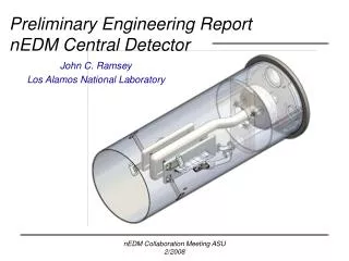
Steel tank Theoretical configuration of central detector Outer acrylic tank Inner acrylic tank PMT Central detector Steel tank of the veto detector
Main features : • Three layers : - steel tank outmost (304L) - outer acrylic tank - inner acrylic tank • Different liquids filled in each tank; • PMTs uniformly installed inside the outmost tank; • ~100 tons weight in total; • Mounted inside the steel tank of veto detector; • Immersed in water; • Removable with liquids in all tanks
Construction of the steel tank Diameter: 5 m Height: 5 m Wall thickness: 10 mm Weight: 15 tons Watertight: necessary O-ring Access ports on the openable top cover Bolted flange joint Lifting eyes
Detector installation adjustable for orientation turnbuckle
Another option for installation meansby mating-conical surfaces Advantage: to be easy mated and oriented Possible problem: mating-surfaces damaged by over load during assembly Conical surfaces
Finite Element Analysis for steel tank Load condition: tank structure filled with liquids Constraint condition: bottom annular surface was constrained The max. stress: 108 MPa The max. deformation: 2.8 mm Stress result Unit:Pa Deformation result Unit:m
Preliminary Design of acrylic tanks -Structure and analysis Main features: • Two homocentric acrylic • tanks mounted inside the • steel tank • Both immersed in liquids • Each of them filled with liquids • Quite similar structures • The same loads cases • Different dimensions • Ports(pipes) are needed as • accesses
The outer acrylic tank Diameter: 4100 mm Height: 4100 mm Wall thickness: 10 mm Ribs thickness: 10 mm Top and bottom covers thickness: 15 mm Weight : 1.4 ton
Analysis and Calculation Just static loads analysis (seismic impact and other shock loads were not considered) Three kinds of load conditions are considered: 1). Gravity only - to check the intensity when it is empty after fabrication. 2). Immersed (suspended) in liquids entirely - both the inside and outside of the tank are pressed by the different liquids, even the liquids in the same levels the different densities of the them also cause this pressure. 3). Differential pressure loads caused by the liquids levels - only happen when we can’t fill the tanks with different liquids inside and outside at the same level simultaneously.
FEA Calculation result The max. stress: ~2.7MPa The max. deformation: 1 mm 1) Only under gravity Stress result Unit:Pa Deformation result Unit:m
The max. stress: ~ 3.9 MPa The max. deformation: ~ 6.2 mm Acrylic net density: 1.19-0.85=0.34 t/m3 Given density differential: 0.05 t/m3 The loads in proportion as deepness of the liquid. 2) Entirely immersed (suspended) in the liquids
3). Differential pressure loads caused by the different liquids levels Given differential pressure: Caused by 100mm deep liquids with density of 850kg/m3 (the density deferential of inside and outside liquids was ignored) The max. stress: 3.1 MPa The max. deformation: 2.5 mm
The inner acrylic tank Diameter: 3200 mm Height: 3200 mm Wall (ribs)thickness: 10 mm Top and bottom covers thickness: 15 mm Weight:0.9 ton Three loads cases, quite similar with the outer acrylic tank . There should be better simulated result according to it’s smaller size and higher location. So no need to check it again.
All the calculation results verified : -the given acrylic tanks structures are reasonable; -adding ribs can well control the deformation and stress and also strengthen the rigidity and intensity without thicker wall Further given detector configuration : (According to the acrylic tanks structures)
Summary • 1) The steel tank: • Basic structure design was proved reasonable with FEA; • Specific design with more accessorial structures will be considered further; • It could be feasible to manufacture after engineering design done: • 2) The acrylic tanks: • Basic structure design are roughly simulated with FEA; • FEA results could help us know how to optimize the design models; • It is necessary to study structure design further: • - to control the deformation as minimum as possible with reasonable wall • thickness; • - to keep the acrylic tanks fixed inside the steel tank; • - to ensure safety for tank structure in different load conditions; • - to study acrylic materials properties by testing the typical samples; • - to make sure manufacture procedures could be realized and meet our design • requirements.