Bracing Example
Bracing Example. Understanding AS1684. Residential Timber Framed Construction. Wind classification - C2 Split Level Dutch gable roofs Ceiling height 2560mm Eaves 600mm Roof pitch 25 o. Bracing Example. 900. 1604 + depth roof frame. North elevation. C2 Split level

Bracing Example
E N D
Presentation Transcript
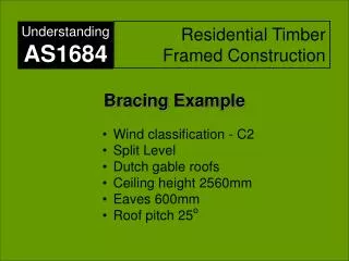
Bracing Example Understanding AS1684 Residential Timber Framed Construction • Wind classification - C2 • Split Level • Dutch gable roofs • Ceiling height 2560mm • Eaves 600mm • Roof pitch 25o
Bracing Example 900 1604 + depth roof frame North elevation • C2 • Split level • Dutch gable roofs • Ceiling height 2560 • Eaves 600mm • Roof pitch 25o 2077 + depth of roof frame 1120 East elevation
Wind Direction 2 Level 2 Level 1 Wind direction 1 Wind direction 2 Level 1 and Level 2 Wind Direction 1
Wind Direction 2 Level 3 Level 3 Wind Direction 1
Bracing Design Process(Clause 8.3.1) 1. Determine the wind classification Clauses 1.4.2 & 1.5 & AS4055/AS/NZS1170.2 2. Determine the wind pressure Clause 8.3.2 & Tables 8.1 to 8.5 3. Determine the area of elevation Clause 8.3.3 and Figure 8.2(A) or (B) 4. Calculate the racking force Clause 8.3.4 and Tables 8.1 to 8.5 5. Design the bracing systems - Sub-floors Clause 8.3.5, Fig 8.4, Tables 8.7 - 8.16, C1 only - Walls Clause 8.3.6, Tables 8.18 and 8.19 6. Check even distribution and spacing Clause 8.3.6.6 and 8.3.6.7, Tables 8.20 – 8.21 7. Connection of bracing to Clause 8.3.6.9 and 8.3.6.10, Table 8.23 roof/ceilings at walls and floors and Figs 8.5 – 8.6 AS1684.3 pg108
1. Determine the Wind Classification • Refer Clause 1.4.2 [pg 9] and AS 4055 or AS/NZS 1170.2 C2 (provided by structural engineer, building professional or local building authority)
2. Determine the wind pressure (for both wind directions) • See Clause 8.3.2 [pg 108] also • Tables 8.1 to 8.5 [pgs 112–120] • Need: • the roof pitch, • the width of the building, and • whether there are any flat walls, skillion ends, gable (or Dutch gables) or hip ends. • Complex designs may require separate pressures within the one wind direction as is the case in this example.
Dutch Gables In this example, the house has Dutch gables which are neither a full gable or a hip end as described by the pressure tables in AS 1684.3. It is recommended that where the height of the Dutch gable (a) is equal to or less than half the full height to the ridge (h), that the Dutch gable end be treated as a hip end. If ‘a’ is greater than 1/2h, then treat the Dutch gable end as a full gable end. a h Dutch gable
1 2.1 Determine the wind pressure (for Wind direction 1) • See Table 8.1 [pg 112] and Table 8.2 [pg 113] • Split the house into it’s two components • Two storey section with Dutch gable • Single storey hip roof (long length of building) Dutch gable end Hip roof long side
1 2.1 (cont) Determine the wind pressure (for Wind direction 1) • For each section, determine the wind pressure for each level • Two storey section with Dutch gable - Level 3 (upper storey of two storey) • - Level 1 (lower storey of two storey) • Single storey hip roof (long length of building) • Level 2 (single storey) • Subfloor (lower storey of two storey) Two storey Dutch gable end Two storey Single storey Single storey Hip roof long side
2.1 (cont) Determine the wind pressure (for Wind direction 1) Two storey section with Dutch gable - Level 3 (upper storey of two storey) Dutch Gable > ½ height of ceiling to ridge, therefore treat as a full gable end. Dutch gable > ½ Height ceiling to ridge Two storey Dutch gable end treated as a full gable
2.1 (Cont) Determine the wind pressure (for Wind direction 1 – Dutch gable end treated as a full gable) Dutch Gable > ½ height of ceiling to ridge, therefore treat as a full gable end. • See Table 8.1 [pg 112] Dutch gable > ½ Height ceiling to ridge Pressure (Assuming gable end) = 2.1 kPa (kN/m2) 1
2.1 (cont) Determine the wind pressure (for Wind direction 1) Two storey section with Dutch gable - Level 1 (lower storey of two storey) Dutch Gable > ½ height of ceiling to ridge, therefore treat as a full gable end. Dutch gable > ½ Height ceiling to ridge Two storey Dutch gable end
2.1 (cont) Determine the wind pressure (for Wind direction 1 gable end) • See Table 8.1 [pg 112] Dutch gable > ½ Height ceiling to ridge 2560 2400 2600 Pressure (Assuming gable end) = 2.1 kPa (kN/m2) 1
2.1 (cont) Determine the wind pressure (for Wind direction 1 – hip end long side of building) Single storey section - Level 2 (single storey) Single storey hip roof long side
Wind direction 1 Level 1 and Level 2 Wind direction 2 Level 3
2.1 (cont) Determine the wind pressure (for Wind direction 1 – hip end long side of building) • See Table 8.2 [pg 113] Single storey - hip roof - long side Pressure = 1.7 kPa (kN/m2) Building Width is 8.91m, but say 9.0m, as interpolation would not gain a lot in this case 1
2.1 (cont) Determine the wind pressure (for Wind direction 1 – hip end long side of building) • See Table 8.3 [pg 115] Lower storey of two storey or sub-floor of single storey Pressure = 1.9 kPa (kN/m2) Building Width is 8.91m, but say 9.0m, as interpolation would not gain a lot in this case 1
2 2.2 Determine the wind pressure (for Wind direction 2 ) As the wind in direction 2 can come from either side onto the east or west elevation, a decision is required on how to account for the worst case. The house is also split level, so other decisions are also required on how the wind will be distributed into bracing walls in each level. This matter will be discussed later. Hip roof long side West elevation Dutch gable end North elevation East elevation
2 • 2.2 (cont) Determine the wind pressure • (for Wind direction 2 – Hip end – Long length of building or from Dutch gable end) Discussion As can be seen from the elevation, the single storey (Level 2) section of the house falls almost entirely within the area envelope of the two storey section. The rear patio is assumed to remain open. The front porch is assumed to be closed one end by lattice. East elevation Also, as the height of the Dutch gable on the east elevation is equal or less than half the overall height to the ridge of the roof, this can be treated as a hip end similar to the hip roof from the west elevation. This section of gable will therefore not result in greater forces than that of the hip roof so it can be ignored in this regard. It is therefore recommended to consider the wind for Direction 2 on the two storey section, and make allowance for any additional small areas of elevation (as shown in orange) outside of the two storey section and account for these forces appropriately where these areas are also considered as a hip.
Interpolation permitted but not necessary Actual6.880 1.6 6.9
2.2 (cont) Determine the wind pressure • (for Level 3, Wind direction 2 – Hip end – • Long length of building ) • See Table 8.2 [pg 113] Roof pitch 250 W = 6.88 Pressure (hip roof - long side) = 1.6 kPa (kN/m2)
Interpolation permitted but not necessary Actual6.880 1.9 6.9
W = 6.88 • 2.2 (cont) Determine the wind pressure • (for Level 1, Wind direction 2 – Hip end – • Long length of building ) • See Table 8.3 [pg 115] Roof pitch 250 Pressure (hip roof - long side) = 1.9 kPa (kN/m2)
2.2 (cont) Determine the wind pressure (for Level 1, Wind direction 2 – Short end of building - Hip end ) • See Table 8.4 [pg 117] Note: The additional areas highlighted in orange, outside the envelope of the two-storey section are considered as pressure on a hip end (rather than gable), as the height of the Dutch gable on this elevation is less than ½ the height from ceiling to to the ridge. Roof pitch 250 Width = 10.06 Pressure (Hip roof end of building ) = 1.8 kPa (kN/m2)
2.2 (cont) Determine the wind pressure • (for Sub-floor of Level 1, Wind direction 2 – Hip end ) Note: Bracing of the sub-floor (indicated in orange) is not required for wind direction 2 as the pressures or forces will be taken by the Level 1 bracing of the two storey section of the house. However, some consideration of the small additional areas as indicated previously may need to be added to the Level 1 forces. 2
2.2 (cont) Determine the wind pressure • Summary of Pressures Direction 1 Direction 2 Level 3 2.1 kN/m2 (gable) Level 3 1.6 kN/m2 (hip) Level 1 2.1 kN/m2 (gable) Level 1 & 2 1.9 kN/m2 (hip) Level 2 1.7 kN/m2 (hip) Level 1 & 2 1.8 kN/m2 (hip) Level 2 subfloor 1.9 kN/m2 (hip)
3.1 Determine the Area of Elevation Discussion Whilst the area/s of elevation should be determined relatively accurately, high levels of precision are not really warranted and therefore use of calculation methods (as used in this example), planimeters or by scaling from drawings would all be acceptable. Note: The area of elevation of triangular portion of eaves up to 1000mm wide may be ignored . See Note 3 to Figures 8.2 (A, B & C), pg 109 – 111 The following method has been used in this example to calculate the area of elevation of the triangular roof section: Area = W/2 x W/2Tan’X’ + 0.15 x W The triangular part of eaves is ignored. ‘X’ 150 mm nominal allowance for depth roof frame, battens and roofing. Increase this if necessary i.e. for exposed rafter roofs. W
3.1 Determine the Area of Elevation (for Wind Direction 1 – Gable end – Level 3) (Eaves 600mm, roof pitch 250) • Height FCL to ridge: • = 6880/2 x Tan 250 • = 3440 x 0.47 • = 1604 mm. Say 1.6 m • Area of gable = 3.44 x 1.6 • = 5.50 m2 • Area due to depth of roof frame (assume 150 mm) = 0.15 x 6.88 = 1.03 m2 • Area of wall = ½ Ceiling height x width • = 2.56/2 x 6.88 • = 8.81 m2 Gable End Area Hip End Area 600 mm 1604 mm 1280 mm 6880 mm 6670 mm Total Gable End Area – Level 3 = 5.5 + 1.03 + 8.81 = 15.34 m2 say 15.3 m2
3.1 (Cont) Determine the Area of Elevation (for Wind Direction 1 – Gable end – Level 1) (Eaves 600mm, roof pitch 250) Hip End Area Gable End Area Area of gable = 3.44 x 1.6 (same as before) = 5.50 m2 Area due to depth of roof frame (assume 150 mm) = 0.15 x 6.88 = 1.03 m2 Area of wall = (wall height level 3 + floor depth + ½ wall height level 1) x width = (2.56 + 0.2 + 1.2) x 6.88 = 27.24m2 3440 mm 600 mm 1604 mm 3960 mm 6880 mm 6670 mm Total Gable End Area – Level 3 = 5.5 + 1.03 + 27.24 = 33.77, say 33.8 m2
3.1 (Cont) Determine the Area of Elevation (for Wind Direction 1 – Hip end – Level 2) (Eaves 600mm, roof pitch 250, for purpose of this example assume Dutch gable is ½ height from FCL to ridge, width of Dutch gable end is 8910 mm) Hip Roof • Height FCL to ridge = 8910/2 x Tan 250 • = 4455 x 0.47 • = 2077 mm, say 2.08 m • Depth of roof frame = 0.15 m (assumed) • Total height to ridge = 2.08 + 0.15 = 2.23 m • Height Dutch gable = 2.23/2 = 1.12 m • Offset of Dutch gable = 1.12/tan 250 • = 2.40 m • Area of roof = length x height to ridge – ¾ blue area • = (6.67 x 2.23) – (0.75 x 2.4 x 2.23) • = 14.87 – 4.01 • = 10.86 m2 • Area of wall = ½ wall height level 2 x width • = 2.56/2 x 6.67 • = 8.54 m2 2400 mm 2230 mm 6670 mm Total Area – Level 2 = 10.86 + 8.54 = 19.4 m2
3.1 (Cont) Determine the Area of Elevation (for Wind Direction 1 – Hip end – sub-floor of Level 2) (Eaves 600mm, roof pitch 250, assume Dutch gable is ½ height to ridge, width of Dutch gable end is 8910 mm) Hip Roof Area of roof and wall for Level 2 as previously calculated = 19.4 m2 Additional area of lower half of Level 2 wall + area of ½ the height of the sub-floor (shaded blue) is to be added to the above area, to get the total area of elevation required for the sub-floor bracing. = length x (1/2 wall height + ½ the sub-floor height) = 6.67 x (2.56/2 + 1.05/2) = 12.04 m2 1805 mm 1050 mm 6670 mm Total Area – Level 2, sub-floor = 19.4 + 12.04 = 31.44 , say 31.4 m2
3.1 (Cont) Determine the Area of Elevation (for Wind Direction 2 – Hip roof – Level 3) (Eaves 600mm, roof pitch 250) Height from FCL to ridge is 1604 mm. Depth of roof frame = 150 mm Total Height FCL to top of ridge = 1754 mm Height of Dutch gable is 900 mm. Overhang on Dutch gable is 300 mm. Total length of ridge that is missing (blue shading) is therefore approximately = 2 x (900 – 300) = 1200 mm. Roof area is = (8.91 x 1.754) – (1.2 x 0.90) = 15.63 - 1.08 = 14.55 m2 Area of wall = 8.91 x 2.56/2 = 11.4 m2 900 mm (Truss spc.) Hip Roof 300 mm 900 mm 1754 mm 8910 mm Total Area – Level 3 = 14.55 + 11.4 = 25.95, say 26.0 m2
3.1 (Cont) Determine the Area of Elevation (for Wind Direction 2 – Hip roof - Level 1) (Eaves 600mm, roof pitch 250) Area of level 3 = 26 m2 Area of lower half of Level 3 and upper half of Level 1 (blue shading) is: = (2560/2 + 200 + 2400/2) x 8910 = (1.28m + 0.2 m + 1.2m) x 8.91m = 23.9 m2 Hip Roof 8910 mm Total Area – Level 1 = 26 + 23.9 = 49.9 m2
3.1 (Cont) Determine the Area of Elevation (for Wind Direction 2 – Hip roof - Level 1 – additional small areas, shaded blue Eaves 600mm, roof pitch 250) Note: For the additional areas, the full height of the wall sections for Level 2 have been used as the loads are assumed to be shared by both Levels 1 and 2 Hip Roof Front porch assuming one end closed in approximately = 3.6/2x 1.15 = 2.07 m2 Rear patio gable, assuming not filled in, and additional wall area under gable approximately = 2.55 x tan25 x 2.55/2 + 0.6 x 1.55 = 1.51 + 0.93 = 2.44 m2 2600 1150 2550 Total additional areas – Level 1 = 2.07 + 2.44 = 4.51m2 say 4.5 m2 Wind direction 2
3.1 (cont) Determine the Area of Elevation • Summary of Areas Direction 1 Direction 2 Level 3 15.3 m2 (gable) Level 3 26.0 m2 (hip) Level 1 33.8 m2 (gable) Level 1 & 2 49.9 m2 (hip) Level 2 19.4 m2 (hip) Level 1 & 2 Additional areas 4.5 m2 (hip) Level 2 subfloor 31.4 m2 (hip)
4. Calculate the racking force (for both Wind Directions) • Use the formula: • Racking Force = Area of Elevation x Wind Pressure • (kN) (m2) (kPa) - (kN/m2) • For complex elevations, combine the results of separate calculations to end up with a total racking force in each of the two wind directions.
4. Calculate the racking force (for both Wind Directions) Use the formula: Racking Force = Area of Elevation x Wind Pressure (kN) (m2) (kN/m2) Example: Total racking force for:- Wind Direction 1, Level 2 Hip= 19.4 m2 x 1.7kN/m2 = 32.98, say 33.0 kN Example: Total racking force for Wind Direction 2, Levels 1 & 2 Hip = 49.9 m2 x 1.9 kN/m2 = 94.8 kN Additional areas = 4.5 m2 x 1.8 kN/m2 = 8.1 kN Total = 102.9 kN
4. Calculate the racking forces (Summary of racking forces for both Wind Directions) Direction 1 Direction 2 Level 3 32.1 kN Level 3 41.6 kN Level 1 71.0 kN Level 1 & 2 94.8 kN Level 2 33 kN Level 1 & 2 Additional areas 8.1 kN Level 2 subfloor 59.7 kN
Distribution of racking forces Discussion: Wind direction 1 Distribution of racking forces is relatively simple in this direction. Consider the house broken into two parts – the two storey section (Levels 1 and 3) and the single storey section (Level 2). The racking forces that occur on each section should be distributed into that section. The racking forces should also be distributed in proportion to the forces that occur on each level in each section. Bracing of the sub-floor for Level 2 will be discussed later. 33kN 71.0kN 32.1kN Level 3 Level 1 Level 2 Wind direction 1
Distribution of racking forces Discussion: Wind direction 2 Distribution of racking forces in this direction is more complicated. It is assumed that Level 2 is integrally tied and connected to Levels 1 and 3, and forces can therefore be distributed across these levels. Level 3 should be designed as ‘stand alone’, and therefore does not contribute to forces in Level 2. It is suggested that up to 1/2 of the forces that occur on Level 1 can be distributed into Level 2 in addition to the force due to the small additional areas. The forces to be distributed in Level 2 will therefore be equal to the difference between 94.8 kN (Level 1) and what is actually taken by Level 1 (57.6 kN see later) , (94.8 – 57.6 = 37.2 kN + 8.1 kN = 45.3 kN) Bracing of the sub-floor for Level 2 will be discussed later. 94.8 kN 8.1 kN 57.6 kN 45.3 kN 41.6 kN Level 1 Level 2 Level 3 Wind direction 2
Distribution of racking forces West elevation 2
5. Design the wall bracing systems Wind direction 1 - Level 1 As the racking force is of a significant magnitude, relatively strong bracing walls will be required. As an initial start, assume bracing walls will be plywood rated at 6.4kN/m, min panel length 600 mm (Method A) – Table 8.18 (h) [pg 140] Therefore length of bracing wall required = 71.0/6.4 = 11.09. say 11.0 m NOTE: Bracing should initially be placed in external walls and, where possible, at the corners of the building –Clause 8.3.6.6 [pg 148]. 71.0 kN
Wind direction 1 - Level 1 Minimum panel length for Plywood is 600 mm for Type A bracing Clause 8.3.6.5(a) [pg 144] Wall 1. For LH garage wall, available wall length is 900 + 600 (corners) + 3600 = 5100 mm 5.1 x 6.4kN/m = 32.6 kN Wall 2 2 x 1.2 m panels = 2.4 m x 6.4 = 15.4 kN Wall 3 1 x 0.9 m = 0.9 x 6.4 = 5.7 kN Wall 4 Available length is 4.4m but use 4.2 x 6.4 = 26.9 kN TOTAL = 32.6 + 15.4 + 5.7 + 26.9 = 80.6 kN therefore satisfactory Note: Wall 3 could be deleted and still OK. (1) (2) (3) (1) 71.0 kN (4) (1)