Connections and Bracing Configurations
Connections and Bracing Configurations. Forces On Structures. Forces from gravity, wind, and seismic events are imposed on all structures Forces that act vertically are gravity loads
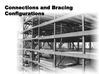

Connections and Bracing Configurations
E N D
Presentation Transcript
Forces On Structures • Forces from gravity, wind, and seismic events are imposed on all structures • Forces that act vertically are gravity loads • Forces that act horizontally, such as stability, wind and seismic events (the focus of this discussion) require lateral load resisting systems to be built into structures • As lateral loads are applied to a structure, horizontal diaphragms (floors and roofs) transfer the load to the lateral load resisting system Structural Steel Frame Elevation
Initial System Planning • The type of lateral load resisting system to be used in a structure should be considered early in the planning stage • Lateral stability as well as architectural needs must be met • The three common lateral load resisting systems are: • Braced Frames • Rigid Frames • Shear Walls 3 1 Chevron Braced Shear Wall Rigid Horiz. Diaphragm (Floor or Roof) Rigid Frame X Braced 2 1 (Adapted from AISC 2002)
Braced Frames and Rigid Frames This presentation focuses on braced frames (left) and rigid frames (right)
Steel Frame Connection Types The Specification for Structural Steel Buildings (AISC 2005) defines two types of connections: • Simple Connections (above left) • Moment Connections (above right) • Fully-Restrained and Partially-Restrained
Steel Frame Connection Types (AISC) • All connections have a certain amount of rigidity • Simple connections (A above) have some rigidity, but are assumed to be free to rotate • Partially-Restrained moment connections (B and C above) are designed to be semi-rigid • Fully-Restrained moment connections (D and E above) are designed to be fully rigid
Simple Connections • Designed as flexible connections • Connections are assumed to be free to rotate • Vertical shear forces are the primary forces transferred by the connection • Require a separate bracing system for lateral stability • The following few slides show some common simple framing connections
Common Simple Connections Single Plate Connection (Shear Tab) A plate is welded to the supporting member and bolted to the web of the supported beam Double Angle Connection The in-plane pair of legs are attached to the web of the supported beam and the out-of-plane pair of legs to the flange or web of the supporting member (Green, Sputo, and Veltri)
Common Simple Connections Shear End Plate Connection A plate is welded perpendicular to the end of the supported web and attached to the supporting member Single Angle Connection One leg is attached to the web of the supported beam and the other leg to the flange or web of the supporting member (Green, Sputo, and Veltri)
Common Simple Connections Seated Connection An angle is mounted with one leg vertical against the supporting column, and the other leg provides a “seat” upon which the beam is mounted A stabilizer connection is also provided at the top of the web Tee Connection The stem of a WT section is connected to the supported member and the flange attached to the supporting member (Green, Sputo, and Veltri)
Moment Connections • Designed as rigid connections which allow little or no rotation • Used in rigid frames • Moment and vertical shear forces are transferred through the connection • Two types of moment connections are permitted: • Fully-Restrained • Partially-Restrained
Common FR Connections Bolted Extended End-Plate Connection A plate is welded to the flanges and web of the supported member and bolted with high-strength bolts to the supporting column Welded Flange Connection Complete-joint-penetration groove welds directly connect the top and bottom flanges of the supported member to the supporting column A shear connection on the web is used to transfer vertical shear forces (Green, Sputo, and Veltri)
Common PR Connections PR Moment Connection – Wind Only A double angle simple connection transfers vertical shear forces while top and bottom flange plates resist moment forces produced by wind Note that the size of the flange plate is relatively small in comparison to the beam flange Top and Bottom Angle with Shear End Plate Connection Angles are bolted or welded to the top and bottom flanges of the supported member and to the supporting column A shear end plate on the web is used to transfer vertical shear forces
Rigid Frames • Rigid frames, utilizing moment connections, are well suited for specific types of buildings where diagonal bracing is not feasible or does not fit the architectural design • Rigid frames generally cost more than braced frames
Braced Frames • Diagonal bracing creates stable triangular configurations within the steel building frame • Braced frames are often the most economical method of resisting wind loads in multi-story buildings • Some structures, like the one pictured above, are designed with a combination braced and rigid frame to take advantage of the benefits of both
Temporary Bracing • Structural steel frames require temporary bracing during construction • Temporary bracing is placed before plumbing up the structural frame • This gives the structure temporary lateral stability • Temporary bracing is removed by the erector
Temporary Bracing • In a braced frame, temporary bracing is removed after final bolt-up is complete and the permanent bracing system is in place • In a rigid frame, temporary bracing is removed after final bolt-up is complete
Concentric Braced Frames • Bracing is concentric when the center lines of the bracing members intersect • Common concentric braced frames used in buildings today include: • X brace (above left) • Two story X’s • Chevron (above right) • Single diagonals • X bracing is possibly the most common type of bracing • Bracing can allow a building to have access through the brace line depending on configuration
X Bracing X Bracing Roof Floor Floor 1st Floor Typical floor plan with X bracing X-braced building elevation • The diagonal members of X bracing go into tension and compression similar to a truss • The multi-floor building frame elevation shown above has just one braced bay, but it may be necessary to brace many bays along a column line • With this in mind it is important to determine the locations of the braced bays in a structure early in a project
X Bracing • Connections for X bracing are located at beam to column joints • Bracing connections may require relatively large gusset plates at the beam to column joint • The restriction of space in these areas may have an impact on the mechanical and plumbing systems as well as some architectural features
Chevron Bracing Chevron Bracing Roof Floor Floor 1st Floor Chevron “V” “K” Typical floor plan with Chevron bracing Elevation with several bracing configurations • The members used in Chevron bracing are designed for both tension and compression forces • Chevron bracing allows for doorways or corridors through the bracing lines in a structure • A multi-floor frame elevation using Chevron bracing is shown above
Chevron Bracing • Chevron bracing members use two types of connections • The floor level connection may use a gusset plate much like the connection on X braced frames • The bracing members are connected to the beam/girder at the top and converge to a common point • If gusset plates are used, it is important to consider their size when laying-out mechanical and plumbing systems that pass through braced bays
Eccentrically Braced Frames Stiffeners Link Beam or Girder Gusset Eccentric Brace Eccentric brace with typical brace to beam connection (Adapted from AISC 2002) • Eccentric bracing is commonly used in seismic regions and allows for doorways and corridors in the braced bays • The difference between Chevron bracing and eccentric bracing is the space between the bracing members at the top gusset connection • In an eccentrically braced frame bracing members connect to separate points on the beam/girder • The beam/girder segment or “link” between the bracing members absorbs energy from seismic activity through plastic deformation
Eccentrically Braced Frames • Eccentrically braced frames look similar to frames with Chevron bracing • A similar V shaped bracing configuration is used
Eccentrically Braced Frames (EERC 1997) Eccentric single diagonals may also be used to brace a frame
Combination Frames Moment frame Moment resisting Chevron braced Bracing Combination Frame • As shown above (left) a braced frame deflects like a cantilever beam while a moment resisting frame deflects more or less consistently from top to bottom • By combining the two systems, reduced deflections can be realized • The combination frame is shown above right
Combination Frames O = Combined Frames X = Chevron or “K” Bracing = Moment Resisting (AISC 1991) • The plot shows the moment resisting frame alone, the braced frame alone, and the combined frame • The same wind load was used for each frame model
References Earthquake Engineering Research Center, (EERC). (1997). W. G. GoddenStructural Engineering Slide Library. Godden J119. Available at: http://nisee.berkeley.edu/bertero/html/recent_developments_in_seismic_design_and_construction.html. Viewed August, 2004. Green, P. S., Sputo, T., and Veltri, P. (n.d.). Connections Teaching Toolkit – A Teaching Guide for Structural Steel Connections. American Institute of Steel Construction, Inc. Chicago, IL.