Lecture 06 Logical Effort
330 likes | 590 Vues
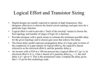
Lecture 06 Logical Effort. ENGR 3430 – Digital VLSI Mark L. Chang Spring ’06. Why Logical Effort?. Important questions for circuit designers What is the best circuit topology for a function? How many stages of logic give least delay? How wide should the transistors be?

Lecture 06 Logical Effort
E N D
Presentation Transcript
Lecture 06Logical Effort ENGR 3430 – Digital VLSI Mark L. Chang Spring ’06
Why Logical Effort? • Important questions for circuit designers • What is the best circuit topology for a function? • How many stages of logic give least delay? • How wide should the transistors be? • Logical effort is a method to make these decisions • Uses a simple model of delay • Allows back-of-the-envelope calculations • Helps make rapid comparisons between alternatives • Emphasizes remarkable symmetries • Sutherland, Sproull, Harris
Delay in a Logic Gate • Express delays in process-independent unit t = 3RC 12 ps in 180 nm process 40 ps in 0.6 mm process
Delay in a Logic Gate • Express delays in process-independent unit • Delay has two components
Delay in a Logic Gate • Express delays in process-independent unit • Delay has two components • Effort delayf = gh (a.k.a. stage effort) • Again has two components
Delay in a Logic Gate • Express delays in process-independent unit • Delay has two components • Effort delay f = gh (a.k.a. stage effort) • Again has two components • g: logical effort • Measures relative ability of gate to deliver current • g 1 for inverter
Delay in a Logic Gate • Express delays in process-independent unit • Delay has two components • Effort delay f = gh (a.k.a. stage effort) • Again has two components • h: electrical effort = Cout / Cin • Ratio of output to input capacitance • Sometimes called fanout
Delay in a Logic Gate • Express delays in process-independent unit • Delay has two components • Parasitic delay p • Represents delay of gate driving no load • Set by internal parasitic capacitance
Computing Logical Effort • DEF: Logical effort is the ratio of the input capacitance of a gate to the input capacitance of an inverter delivering the same output current. • Measure from delay vs. fanout plots • Or estimate by counting transistor widths
Catalog of Gates • Logical effort of common gates
Catalog of Gates • Parasitic delay of common gates • In multiples of pinv (1)
Example: Ring Oscillator • Estimate the frequency of an N-stage ring oscillator Logical Effort: g = Electrical Effort: h = Parasitic Delay: p = Stage Delay: d = Frequency: fosc =
Example: FO4 Inverter • Estimate the delay of a fanout-of-4 (FO4) inverter Logical Effort: g = Electrical Effort: h = Parasitic Delay: p = Stage Delay: d =
Multistage Logic Networks • Logical effort generalizes to multistage networks • Path Logical Effort • Path Electrical Effort • Path Effort
Multistage Logic Networks • Logical effort generalizes to multistage networks • Path Logical Effort • Path Electrical Effort • Path Effort • Can we write F = GH?
Paths that Branch • Consider paths that branch: G = H = GH = h1 = h2 = F = GH?
Branching Effort • Introduce branching effort • Accounts for branching between stages in path • Now we compute the path effort • F = GBH Note:
Multistage Delays • Path Effort Delay • Path Parasitic Delay • Path Delay
Designing Fast Circuits • Delay is smallest when each stage bears same effort • Thus minimum delay of N stage path is • This is a key result of logical effort • Find fastest possible delay • Doesn’t require calculating gate sizes
[Extra Credit] • Prove • That delay is minimized when each stage bears the same effort • Prove for non-branching two-stage circuit • Prove generality • N stage • Branching Gate 1 Gate 2 C3 Input capacitance: C1 C2 Logical effort: g1 g2 Parasitic delay: p1 p2
Gate Sizes • How wide should the gates be for least delay? • Working backward, apply capacitance transformation to find input capacitance of each gate given load it drives. • Check work by verifying input cap spec is met.
Example: 3-stage path • Select gate sizes x and y for least delay from A to B
Example: 3-stage path Logical Effort G = Electrical Effort H = Branching Effort B = Path Effort F = Best Stage Effort Parasitic Delay P = Delay D =
Example: 3-stage path • Work backward for sizes y = x =
Best Number of Stages • How many stages should a path use? • Minimizing number of stages is not always fastest • Example: drive 64-bit datapath with unit inverter D =
Derivation • Consider adding inverters to end of path • How many give least delay? • Define best stage effort
Best Stage Effort • has no closed-form solution • Neglecting parasitics (pinv = 0), we find r = 2.718 (e) • For pinv = 1, solve numerically for r = 3.59
Sensitivity Analysis • How sensitive is delay to using exactly the best number of stages? • 2.4 < r < 6 gives delay within 15% of optimal • We can be sloppy! • I like r = 4
Method of Logical Effort • Compute path effort • Estimate best number of stages • Sketch path with N stages • Estimate least delay • Determine best stage effort • Find gate sizes
Limits of Logical Effort • Chicken and egg problem • Need path to compute G • But don’t know number of stages without G • Simplistic delay model • Neglects input rise time effects • Interconnect • Iteration required in designs with wire • Maximum speed only • Not minimum area/power for constrained delay
Summary • Logical effort is useful for thinking of delay in circuits • Numeric logical effort characterizes gates • NANDs are faster than NORs in CMOS • Paths are fastest when effort delays are ~4 • Path delay is weakly sensitive to stages, sizes • But using fewer stages doesn’t mean faster paths • Delay of path is about log4F FO4 inverter delays • Inverters and NAND2 best for driving large caps • Provides language for discussing fast circuits • But requires practice to master