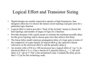
Logical Effort Basics: Components Scaling Reference Guide
470 likes | 497 Vues
Understand how logical effort components scale with width, capacitance, and resistance in high-performance system design.

Logical Effort Basics: Components Scaling Reference Guide
E N D
Presentation Transcript
Logical Effort Components Template Template Width Scaled by a • Input Capacitance increases by a ·Ctemplate • Resistance decreases by Rtemplate / a Vojin G. Oklobdzija: High-Performance System Design
Logical Effort Input Capacitance Coxeox / tox (unit: F/m2) Leff = L – 2xd Cgate = CoxWLeff = CoxWL(1 – 2xd / L) k1 = Cox(1 – 2xd / L) Input Capacitance Cin is the sum of the gate capacitances Cin(inv) = k1WnLn + k1WpLp Scaling all transistor widths by a, scales Cinv by a C = k1aWnLn + k1aWpLp = a Cin Vojin G. Oklobdzija: High-Performance System Design
Logical Effort Resistance R = (r / t) (L / W) ohms Rchannel = Rsheet (L / W) ohms Rsheet = 1 / ( mCox ( Vgs – Vt )) ohms m = surface mobility Rchannel = L / (mCoxW ( Vgs – Vt )) ohms Scaling the transistor width by a factor a, results in: R= L / (mCoxaW ( Vgs – Vt ) ) = Rchannel / a Resistance is inversely proportional to a Vojin G. Oklobdzija: High-Performance System Design
Logical Effort Parasitics Cja junction capacitance per m2 Cjp periphery capacitance per m W width of diffusion region m Ldiff length of diffusion region m Scaling the transistor width by a factor a, results in: Parasitic capacitance scales proportional to a Vojin G. Oklobdzija: High-Performance System Design
thl delay derivation for step input Vojin G. Oklobdzija: High-Performance System Design
Delay derivation (cont.) Saturation: Linear: Vojin G. Oklobdzija: High-Performance System Design
Delay derivation (cont.) Vojin G. Oklobdzija: High-Performance System Design
Delay derivation (cont.) Vojin G. Oklobdzija: High-Performance System Design
Delay derivation (cont.) Substituting R Rchannel = L / (mCox ( Vgs – Vt ) W) ohms Yeilds an RC Delay model k Vojin G. Oklobdzija: High-Performance System Design
tlh delay derivation for step input Concerns: • Vtn and Vtp • mn and mp Must distinguish Rchannel(tlh) and Rchannel(thl) Vojin G. Oklobdzija: High-Performance System Design
Handling Pull-up and Pull-down For tlh we refer to Rchannel as Rup Rup = Lp / (mpCoxWp( Vgs – Vtp )) ohms For thl we refer to Rchannel as Rdown Rdown = Ln / (mnCoxWn( Vgs – Vtn )) ohms For now lets assume that Vdd-Vtp = Vtn Rup = Lp / (mpCoxWp( Vgs – Vt )) ohms Rdown = Ln / (mnCoxWn( Vgs – Vt )) ohms For the same length and width, difference is due to mobility. Vojin G. Oklobdzija: High-Performance System Design
Equalizing Pull-up and Pull-down How to equalize Rup and Rdown Example: Assume 2mn = mp and Lp = Ln Rup = Lp / (0.5mnCoxWp( Vgs – Vt )) ohms Rdown = Ln / (mnCoxWn( Vgs – Vt )) ohms To equalize resistance, Wp = 2Wn When Rup = Rdown, tlh = thl for the same output load Vojin G. Oklobdzija: High-Performance System Design
RC Model for a CMOS logic gate Graphical Representation of RC model: Vojin G. Oklobdzija: High-Performance System Design
RC Model for a CMOS logic gate Can use this model for any static CMOS gate: • Find the equivalent resistance for the pull-up and pull down paths of the logic gate • Assume parasitic only occur at output node Example: 2-input NAND gate (* 2mn = mp) Rup = Rp(a) or = Rp(b) Only 1 transistor on pull-up path… Rdown = Rn(a) + Rn(b) Want Rup = Rdown 2 transistors in the pulldown. Can treat as resistors in series. For inverter occurs when Wp = 2Wn Here occurs when Wp = Wn Vojin G. Oklobdzija: High-Performance System Design
Delay of each gate is the same, right? We can equalize the delay associated with RCout However RCp depends on the gate Is the only difference between gates RCp? Vojin G. Oklobdzija: High-Performance System Design
Delay of each gate is the same, right? We can equalize the delay associated with RCout However RCp depends on the gate Is the only difference between gates RCp? We forgot about Cin We equalized the resistance of each gate, but the capacitance Isn’t the same…. Vojin G. Oklobdzija: High-Performance System Design
Moving to Logical Effort(accounting for Cin) * t refers to the template Gate Template a Scaled Gate Vojin G. Oklobdzija: High-Performance System Design
Logical Effort Gate Delay Model Simplify Analysis by Normalizing to Inverter Template Parasitics Logical Effort Electrical Effort Doesn’t change with a Doesn’t change with a Same derivation can be performed for tlh Vojin G. Oklobdzija: High-Performance System Design
Technology independence Relative delay of gates is ~ technology independent. Allows for comparisons to be fairly accurate across technologies Anyone heard of fanout of four (FO4)? 4C C or C C C C C Before transistor sizing The delay of an inverter Loaded with 4 inverters With transistor sizing The delay of an inverter loaded with 4 identical inverters Can cause some confusion… FO4 is not exactly logical fanout…. Vojin G. Oklobdzija: High-Performance System Design
Examples: Estimating g and p of Gates Inverter NAND2 NOR2 2 2 4 2 4 2 1 1 1 2 g = (2+2)/(2+1) = 4/3 p = [(2+2+2)/(2+1)]pinv = 2pinv g = (4+1)/(2+1) = 5/3 p = [(4+1+1)/(2+1)]pinv = 2pinv g = (2+1)/(2+1) = 1 p = Cp-inv/Cinv = pinv Vojin G. Oklobdzija: High-Performance System Design
Obtaining LE Values from Simulation In real world we don’t have a step input… What do the delay characteristics of a gate look like when simulating? Vojin G. Oklobdzija: High-Performance System Design
130nm Delay of Gates vs. h NOR2 NAND2 Inverter Slope = t = 7.3ps Vojin G. Oklobdzija: High-Performance System Design
Normalized Delay of Gates vs. h t = 7.3ps NOR2: g=1.57, p=1.89 NAND2: g=1.14, p=1.45 Inverter: g=1, p=0.93 Effort Delay Parasitic Delay Vojin G. Oklobdzija: High-Performance System Design
Normalized Delay Estimate of Gates vs. h Note: To simplify analysis Assume Cp-inv = Cinv NOR2: g=5/3, p=2 NAND2: g=4/3, p=2 Inverter: g=1, p=1 Effort Delay Parasitic Delay Vojin G. Oklobdzija: High-Performance System Design
Finding Optimal delay Given Cout = 64Cin How should we size the gates to get the best delay? [Harris, Sutherland] Vojin G. Oklobdzija: High-Performance System Design
LE Path Delay Gate 1 Gate 2 Gate 3 Cout Input Capacitance Cin C2 C3 Logical Effort: g1 g2 g3 Parasitic Delay p1 p2 p3 Stage Effort: f1 f2 f3 • Any n-stage path can be described using Logical Effort Vojin G. Oklobdzija: High-Performance System Design
LE Path Delay Optimization Vojin G. Oklobdzija: High-Performance System Design
LE Path Delay Optimization (cont.) By Definition, Cin and Cout are fixed. Solve for C2 and C3: Minimum delay occurs when stage efforts are equal Vojin G. Oklobdzija: High-Performance System Design
Simplified Path Optimization We want the effort of each stage to be equal. = Path Effort = Stage Effort To quickly solve for F: = Logical Effort of the path Vojin G. Oklobdzija: High-Performance System Design
Delay Optimization Example C2 Cin = 1 C3 C4 Gate 3 1 1 1 Gate 4 1 81 1 Gate 1 1 1 1 Gate 2 1 1 1 g f = gh Ci Total Delay = (84 + 4pinv)t Vojin G. Oklobdzija: High-Performance System Design
Delay Optimization Example C2 C4 C3 Cin = 1 Gate 3 1 40.5 1 Gate 4 1 2 40.5 Gate 1 1 1 1 Gate 2 1 1 1 g f = gh Ci Total Delay = (44.5 + 4pinv)t Vojin G. Oklobdzija: High-Performance System Design
Delay Optimization Example C2 C3 C4 Cin = 1 Gate 3 1 4 10.1 Gate 4 1 2 40.5 Gate 1 1 1 1 Gate 2 1 10.1 1 g f = gh Ci Total Delay = (17.1 + 4pinv)t Vojin G. Oklobdzija: High-Performance System Design
Delay Optimization Example C2 C3 C4 Cin = 1 Gate 3 1 4 10.1 Gate 4 1 2 40.5 Gate 1 1 10.1 1 Gate 2 1 1 10.1 g f = gh Ci Total Delay = (17.1 + 4pinv)t Vojin G. Oklobdzija: High-Performance System Design
Optimal Sizing for Delay C2 C3 C4 Cin = 1 Gate 3 1 3 9 Gate 4 1 3 27 Gate 1 1 3 1 Gate 2 1 3 3 g f = gh Ci Optimal Delay = (12 + 4pinv)t Vojin G. Oklobdzija: High-Performance System Design
Delay Optimization and Sizing Example C2 Cin = 1 C3 C4 Use Logical Effort to optimize sizes for Delay Vojin G. Oklobdzija: High-Performance System Design
Delay Optimization and Sizing Example Cin = 1 C2 C3 C4 Size from output to input using fopt Delay Estimate Vojin G. Oklobdzija: High-Performance System Design
Example 2: Path Optimization C4 C2 Cin = 1 C3 Gate 3 4/3 4/3*3/4 4/3 1 Gate 4 1 81 1 1 Gate 1 1 1 1 1 Gate 2 5/3 5/3*3/5 5/3 1 g f = gh Ci Size Total Delay = (85 + 6pinv)t Vojin G. Oklobdzija: High-Performance System Design
Example 2: Path Optimization C2 C3 C4 Cin = 1 Gate 3 4/3 3.66 8.06 6.04 Gate 4 1 3.66 22.1 22.1 Gate 1 1 3.66 1 1 Gate 2 5/3 3.66 3.66 2.2 g f = gh Ci Size Optimal Delay = (14.64 + 6pinv)t Vojin G. Oklobdzija: High-Performance System Design
Example 2: LE Solution Cin = 1 C2 C3 C4 Size from output to input using fopt S1 = 1, S2 = 2.2, S3 = 6.04, S4 = 22.1 Delay Estimate Vojin G. Oklobdzija: High-Performance System Design
Logical Effort for Multi-path From LE, and Minimum delay occurs when Da = Db or Fa = Fb(ignoring parasitics) Vojin G. Oklobdzija: High-Performance System Design
Logical Effort for Multi-path (cont.) Branching: Ratio of total capacitance to on-path capacitance Vojin G. Oklobdzija: High-Performance System Design
Logical Effort for Multi-path (cont) Substituting C0 and C3 Since Minimum Delay occurs when Da = Db or Fa = Fb Similarly • Branching = 2 when Ga = Gb and Cout1 = Cout2 Vojin G. Oklobdzija: High-Performance System Design
Example 3: Uniform Branching C6 C5 Cout2 = C5+C3 Cin = 1 C2 C4 C3 g f = gh Ci b Gate 3,5 4/3 4/3 1 1 Gate 4,6 1 81 1 1 Gate 1 1 1 1 1 Gate 2 5/3 10/3 1 2 Total Delay = (86.67 + 6pinv)t Vojin G. Oklobdzija: High-Performance System Design
Example 3: Uniform Branching C6 C5 Cout2 = C5+C3 Cin = 1 C2 C4 C3 g f = gh Ci b Gate 3,5 4/3 4.36 5.69 1 Gate 4,6 1 4.36 18.6 1 Gate 1 1 4.36 1 1 Gate 2 5/3 4.36 4.36 2 Optimal Delay = (17.44 + 6pinv)t Vojin G. Oklobdzija: High-Performance System Design
Example 3: LE Solution C6 C5 Cout2 = C5+C3 C2 Cin = 1 C4 C3 Size from output to input using fopt Delay Estimate Vojin G. Oklobdzija: High-Performance System Design
Complex Multi-path Optimization If each path has internal branching, ba and bbare as follows • Note: This solution and previous solution differ from that described in LE book (which is incorrect) Vojin G. Oklobdzija: High-Performance System Design