Download
1 / 7
70 likes | 103 Vues
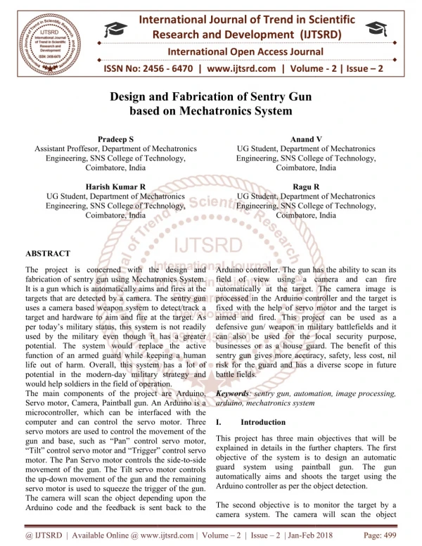
The project is concerned with the design and fabrication of sentry gun using Mechatronics System. It is a gun which is automatically aims and fires at the targets that are detected by a camera. The sentry gun uses a camera based weapon system to detect track a target and hardware to aim and fire at the target. As per today's military status, this system is not readily used by the military even though it has a greater potential. The system would replace the active function of an armed guard while keeping a human life out of harm. Overall, this system has a lot of potential in the modern day military strategy and would help soldiers in the field of operation. The main components of the project are Arduino, Servo motor, Camera, Paintball gun. An Arduino is a microcontroller, which can be interfaced with the computer and can control the servo motor. Three servo motors are used to control the movement of the gun and base, such as "Pan control servo motor, "Tilt control servo motor and "Trigger control servo motor. The Pan Servo motor controls the side to side movement of the gun. The Tilt servo motor controls the up down movement of the gun and the remaining servo motor is used to squeeze the trigger of the gun. The camera will scan the object depending upon the Arduino code and the feedback is sent back to the Arduino controller. The gun has the ability to scan its field of view using a camera and can fire automatically at the target. The camera image is processed in the Arduino controller and the target is fixed with the help of servo motor and the target is aimed and fired. This project can be used as a defensive gun weapon in military battlefields and it can also be used for the local security purpose, businesses or as a house guard. The benefit of this sentry gun gives more accuracy, safety, less cost, nil risk for the guard and has a diverse scope in future battle fields. Pradeep S | Anand V | Harish Kumar R | Ragu R "Design and Fabrication of Sentry Gun based on Mechatronics System" Published in International Journal of Trend in Scientific Research and Development (ijtsrd), ISSN: 2456-6470, Volume-2 | Issue-2 , February 2018, URL: https://www.ijtsrd.com/papers/ijtsrd9434.pdf Paper URL: http://www.ijtsrd.com/engineering/mechanical-engineering/9434/design-and-fabrication-of-sentry-gun-based-on-mechatronics-system/pradeep-s<br>

E N D
International Research Research and Development (IJTSRD) International Open Access Journal n and Fabrication of Sentry Gun based on Mechatronics System International Journal of Trend in Scientific Scientific (IJTSRD) International Open Access Journal ISSN No: 2456 ISSN No: 2456 - 6470 | www.ijtsrd.com | Volume 6470 | www.ijtsrd.com | Volume - 2 | Issue – 2 Design and Fabrication of Sentry Gun based o Pradeep S Department of Mechatronics Anand V Anand V Assistant Proffesor, Department of Mechatronics Engineering, SNS College of Technology, Coimbatore, India Harish Kumar R UG Student, Department of Mechatronics Engineering, SNS College of Technology, Coimbatore, India UG Student, Department of Mechatronics Engineering, SNS College of Technology, Coimbatore, India UG Student, Department of Engineering, SNS College of Technology, Coimbatore, India Ragu R UG Student, Department of Mechatronics Engineering, SNS College of Technology, Coimbatore, India Engineering, SNS College of Technology, Ragu R UG Student, Department of Mechatronics Engineering, SNS College of Technology, UG Student, Department of Mechatronics Engineering, SNS College of Technology, Coimbatore, India ABSTRACT The project is concerned with the design and fabrication of sentry gun using Mechatronics System. It is a gun which is automatically aims and fires at the targets that are detected by a camera. The sentry gun uses a camera based weapon system to detect/track a target and hardware to aim and fire at the target. As per today’s military status, this system is not readily used by the military even though it has a greater potential. The system would replace the active function of an armed guard while keeping a human life out of harm. Overall, this system has a lot of potential in the modern-day military strategy and would help soldiers in the field of operation. The main components of the project are Arduino, Servo motor, Camera, Paintball gun. An Arduino is a microcontroller, which can be interfaced with the computer and can control the servo motor. Three servo motors are used to control the movement of the gun and base, such as “Pan” control servo motor, “Tilt” control servo motor and “Trigger” control servo motor. The Pan Servo motor controls the side movement of the gun. The Tilt servo motor controls the up-down movement of the gun and the remaining servo motor is used to squeeze the trigger of the gun. The camera will scan the object depending upon the Arduino code and the feedback is sent back to the Arduino code and the feedback is sent back to the The project is concerned with the design and fabrication of sentry gun using Mechatronics System. automatically aims and fires at the targets that are detected by a camera. The sentry gun uses a camera based weapon system to detect/track a target and hardware to aim and fire at the target. As per today’s military status, this system is not readily by the military even though it has a greater potential. The system would replace the active function of an armed guard while keeping a human life out of harm. Overall, this system has a lot of day military strategy and oldiers in the field of operation. The main components of the project are Arduino, Servo motor, Camera, Paintball gun. An Arduino is a microcontroller, which can be interfaced with the computer and can control the servo motor. Three to control the movement of the gun and base, such as “Pan” control servo motor, “Tilt” control servo motor and “Trigger” control servo motor. The Pan Servo motor controls the side-to-side movement of the gun. The Tilt servo motor controls ent of the gun and the remaining servo motor is used to squeeze the trigger of the gun. The camera will scan the object depending upon the Arduino controller. The gun has the ability to scan its ew using a camera and can fire automatically at the target. The camera image is processed in the Arduino controller and the target is fixed with the help of servo motor and the target is aimed and fired. This project can be used as a in military battlefields and it can also be used for the local security purpose, businesses or as a house guard. The benefit of this sentry gun gives more accuracy, safety, less cost, nil risk for the guard and has a diverse scope in future Arduino controller. The gun has the ability to scan its field of view using a camera and can fire automatically at the target. The camera image is processed in the Arduino controller and the target is fixed with the help of servo motor and the target is aimed and fired. This project can be used as a defensive gun/ weapon in military battlefields and it can also be used for the local security purpose, businesses or as a house guard. The benefit of this sentry gun gives more accuracy, safety, less cost, nil risk for the guard and has a diverse scope in future battle fields. Keywords: sentry gun, automation, image processing, arduino, mechatronics system I. Introduction : sentry gun, automation, image processing, This project has three main objectives that will be explained in details in the further chapters. The first objective of the system is to design an automatic guard system using paintball gun. The gun automatically aims and shoots the target using the Arduino controller as per the object detection. The second objective is to monitor the target by a camera system. The camera will scan the object camera system. The camera will scan the object This project has three main objectives that will be explained in details in the further chapters. The first objective of the system is to design an automatic guard system using paintball gun. The gun automatically aims and shoots the target using the Arduino controller as per the object detection. The second objective is to monitor the target by a @ IJTSRD | Available Online @ www.ijtsrd.com @ IJTSRD | Available Online @ www.ijtsrd.com | Volume – 2 | Issue – 2 | Jan-Feb 2018 Feb 2018 Page: 499
International Journal of Trend in Scientific Research and Development (IJTSRD) ISSN: 2456 International Journal of Trend in Scientific Research and Development (IJTSRD) ISSN: 2456 International Journal of Trend in Scientific Research and Development (IJTSRD) ISSN: 2456-6470 depending upon the Arduino code and the feedback is sent back to the Arduino controller. The gun has the ability to scan its field of view using a camera and can fire automatically at the target. The camera image is processed in the Arduino controller and the target is fixed with the help of servo motor and the target is aimed and fired. The third objective is to automatically aim and fire at the target. It is a gun which is automatically aimed and fired at the targets that are detected by a camera. The sentry gun uses a camera based weapon system to detect and track a target and hardware to aim and fire at the target. II. PROBLEM IDENTIFICATION PROBLEM IDENTIFICATION he Arduino code and the feedback is sent back to the Arduino controller. The gun has the ability to scan its field of view using a camera and can fire automatically at the target. The camera image is processed in the Arduino controller and the target is xed with the help of servo motor and the target is system can also be further optimized depending on its use but initially it can be used for local security by businesses or home owners. III. Methodology optimized depending on its use but initially it can be used for local security by This project’s methodology has three working stages prototype, prototype and model. In the prototype, to design the sentry gun model using Solid works software. In the prototype, the base design is done and to design the gun position. To design the interior shape. In the model, to design the base using MDF material and construct it. And to design the object scanning software coding using Arduino and to design the working mechanism This project’s methodology has three working stages such as pre-prototype, prototype and model. In the pre-prototype, to design the se Solid works software. In the prototype, the base design is done and to design the gun position. To design the interior shape. In the model, to design the base using MDF material and construct it. And to design the object scanning softw Arduino and to design the working mechanism .Finally the sentry gun is ready to test the target. .Finally the sentry gun is ready to test the target. The third objective is to automatically aim and fire at the target. It is a gun which is automatically aimed and fired at the targets that are detected by a camera. camera based weapon system to detect and track a target and hardware to aim and fire A. Existing Methodology As per today’s military status, this system is not readily used by the military even though it has a greater potential. The system would replace the active function of an armed guard while keeping a human life out of harm. Overall, this system has a lot of potential in the modern-day military strategy and would help soldiers in the field of operation. This would help soldiers in the field of operation. This As per today’s military status, this system is not readily used by the military even though it has a There is a arduino controller which controls the three- There is a arduino controller which controls the three axes motion (Pan motor, Tiltmotor, Therefore it helps to fire at the target. The block diagram of Existing methodology is shown below in Fig.1 would replace the active Tiltmotor, Trigger motor) function of an armed guard while keeping a human life out of harm. Overall, this system has a lot of day military strategy and Therefore it helps to fire at the target. The block diagram of Existing methodology is shown Fig.1. Block diagram of Existing system Fig.1. Block diagram of Existing system @ IJTSRD | Available Online @ www.ijtsrd.com @ IJTSRD | Available Online @ www.ijtsrd.com | Volume – 2 | Issue – 2 | Jan-Feb 2018 Feb 2018 Page: 500
International Journal of Trend in Scientific Research and Development (IJTSRD) ISSN: 2456-6470 Disadvantages of the existing system are Slow response Poor object detection Less sliding movement However in our system these disadvantages are overcome effectively. B. Proposed System The proposed system contains same as the existing system but it enhances the features like sliding movement, motion tracking and improves object detection. The block diagram of proposed methodology is shown below in Fig.2 Fig.2. Block diagram of proposed system IV. COMPONENTS The selection of materials involves the study of their Characteristics, advantages, availability, cost, user friendly property of components that we want to use. In our project, we select each and every component by study thoroughly about them. By proceeding like that only, we have done our selection. The software and device chosen to programming the execution of our idea is Arduino microcontroller. Servomotor Camera and Paintball gun @ IJTSRD | Available Online @ www.ijtsrd.com | Volume – 2 | Issue – 2 | Jan-Feb 2018 Page: 501
International Journal of Trend in Scientific Research and Development (IJTSRD) ISSN: 2456-6470 The detailed description for selecting components is given below: A.ARDUINO The Arduino Mega 2560 is a microcontroller board based on the ATmega2560. It has 54 digital input/output pins (of which 14 can be used as PWM outputs), 16 analog inputs, 4 UARTs (hardware serial ports), a 16 MHz crystal oscillator, a USB connection, a power jack, an ICSP header, and a reset button. It contains everything needed to support the microcontroller; simply connect it to a computer with a USB cable or power it with a AC- to-DC adapter or battery to get started. The Mega is compatible with most shields designed for the Arduino Duemilanove or Diecimila. Arduino can sense the environment by receiving input from a variety of sensors and can affect its surroundings by controlling lights, motors, and other actuators. The microcontroller on the board is programmed using the Arduino programming language (based on Wiring) and the Arduino development environment (based on Processing). Arduino projects can be stand-alone or they can communicate with software on running on a computer (e.g. Flash, Processing, Max MSP). The Arduino board is shown in fig.3 Fig.3.Arduino Mega (source: www.arduino.cc) Open source and extensible software- the Arduino software is published as open source tools available for extension by experienced programmers. The language can be expanded through C++ libraries, and people wanting to understand the technical details can make the leap from Arduino to the AVR C programming language on which it’s based similarly you can add AVRC code directly into Arduino program if you want to. Open source and extensible hardware– the Arduino is based on Atmel’s ATMEGA8 and ATMEGA168 microcontrollers. The plans for the modules are published under a creative common license, so experienced circuit designers can make their own version of the module, extending it and improving it. Even relatively inexperienced users can built the breadboard version of the module in order to understand how it works and save money. The Five Major Benefits of Using Arduino Starter Kits Inexpensive- Arduino boards are relatively in expensive compared to other microcontroller platforms. The least expensive Version of Arduino Module can be assembled by hand, and even the pre-assembled Arduino modules cost less than $50. Cross Platform- the Arduino software runs on Windows, Macintosh OSX, and Linux operating systems. Most Microcontroller systems are limited to windows. Simple, Clear Programming Environment- the Arduino programming environment is easy to-use for beginners, yet flexible enough for advanced users to test advantage of as well. For teachers, it’s conveniently based on the processing programming environment, so students learning to program in that environment will be familiar with the look and feel of Arduino @ IJTSRD | Available Online @ www.ijtsrd.com | Volume – 2 | Issue – 2 | Jan-Feb 2018 Page: 502
International Journal of Trend in Scientific Research and Development (IJTSRD) ISSN: 2456-6470 projects to be the starting point of research. Like DC motors, the signal controlled servos has drawbacks. The largest drawback to servo motors is quickly increasing cost for the increase in torque. Another large drawback is that most stock servo motors only have a 90 degree range of motion. In order to gain a 180 degree range of motion additional charges may apply. In order to keep the cost low and simplicity high, servo motors were chosen to control the pan and tilt directions of the turret. For pulling the trigger, a low cost, low torque servo can be utilized. B.Servo control method Most standard servos have three leads, positive power, negative, and signal. The power lead not only acts as the power source for the servo, but can also be utilized to turn the servo either on or off. The typical input voltage for power is between 4.8 volts and 6.0 volts. The negative power lead should be common ground. The signal lead will control the direction of the servo The primary method of controlling the servo is to send a pulse-width modulation along the signal lead. This pulse-width modulation signals is a fifty hertz square width. The length of each pulse of the square wave controls how far the servo will rotate. For example a pulse of 600 microseconds will rotate the servo arm -90 degrees and a 2400 microsecond pulse will rotate the arm positive 90 degrees. C.Camera The camera will be a vital component in the system design. The sole purpose of the web camera is to provide optics for the system, from there the software will be implemented so the system has object detection. For these implementations to occur, a high definition camera will need to be used. The camera will be attached to paintball gun looking down the barrel for accuracy of the target. The camera will also be connected to the laptop via USB and have a real- time video capturing that will display on the laptop. The camera is shown in fig.5. A.Servo Motor Three servo motors are used to control the movement of the gun and base, such as “Pan” control servo motor, “Tilt” control servo motor and “Trigger” control servo motor. The Pan Servo motor controls the side-to-side movement of the gun. The Tilt servo motor controls the up-down movement of the gun and the remaining servo motor is used to squeeze the trigger of the gun. The Servo Motor configuration isshown in fig.4 Fig 4: Servo Motor configuration To effectively control the autonomous turret, a system of motors should be implemented to allow for full motion and firing. Since the turret is designed to be stationary, it is best to think of the turret as the origin of a spherical coordinate system. This will allow one motor to be dedicated to the pan control, a second motor dedicated to the tilt control and a third motor dedicated to pulling a trigger. Since the turret will remain stationary at the origin, rotational motors will provide easiest control. There are two types of motors that primarily stand out. These choices are a standard DC motor and a signal controlled servo motor, both of which have their own advantages and disadvantages. Advantages to the DC motor include a full 360 degree range of motion, one input, and the availability of high torque. However there are large drawbacks when used in a controls environment. The largest of these drawbacks is the low precision. The motor is either on or off where speed can be adjusted based on the input. In order to accurately control the position a highly accurate microcontroller will most likely be needed. Another large drawback is the significant cost of higher torque motors. Advantages to the signal controlled servos include a lower cost when compared to DC motors, a signal controlled position, and multiple similarly previous Fig.5.camera @ IJTSRD | Available Online @ www.ijtsrd.com | Volume – 2 | Issue – 2 | Jan-Feb 2018 Page: 503
International Journal of Trend in Scientific Research and Development (IJTSRD) ISSN: 2456-6470 heavier requiring greater torque to get it to turn about. The base would be composed of the same MDF wooden housing which would act as the base while a rotating plate hooked up to the horizontal servo. The top section would consist of the gun mount and ammunition. Another option was to create a fixed base with a pan and tilt system mounted on top to mount the gun. D.Paintball gun The gun has the ability to scan its field of view using a camera and can fire automatically at the target. The camera image is processed in the Arduino controller and the target is fixed with the help of servo motor and the target is aimed and fired. The Paintball Gun is shown in fig.6. The Gun Mount Creating a lightweight durable gun mount is a major design challenge the group faces. The gun mount must be very strong to hold up to the vibration and stress of the automatic firing rate. If the gun mount is too heavy the servo motors will have a hard time rotating the gun, but if the mount is too light there is a chance it will break or severely decrease the accuracy of SG’s. The group has a few different options for mounting the paintball gun. The first option is to create a frame for the gun to rest in. This can be done by creating a box made of lightweight metal rods. The rods will support the barrel and the handle of the gun. Two more metal rods will be used to keep the gun straight and accurate. The second option the group is considering is a side mounting for the gun. The mount would be positioned on the left or right side of the gun and have the ability to swivel left, right, up and down. Fig 6: paintball gun The base Possible options for the base include creating a tri-pod with a mounting for the gun at the top. The electronics would be housed in a MDF box and be hooked up to the on-board. This architecture is very similar to a camera mounted on a tripod. The tri-pod must be sturdy enough to remain standing after the rapid firing of gun, if the tri-pod rocks too much SG’s accuracy will suffer greatly. This design would raise the gun off of the ground level and allow for more vertical coverage. The group’s second option is to create a rotating platform for the gun. This option would require a less complex gun mount but would be E.Controller Board This mounting would be very lightweight and keep the sentry compact and offer a less cumbersome mounting. The pan and tilt option requires that the group builds a platform to rest the gun. The Controller Board configuration is shown in fig.7. Fig 7: Controller Board configuration @ IJTSRD | Available Online @ www.ijtsrd.com | Volume – 2 | Issue – 2 | Jan-Feb 2018 Page: 504
The Table 1 which is listed below contains the overall components used in this project. Acknowledgment We take immense pleasure in expressing our humble note of gratitude to our project guide Mr.S.Pradeep Assistant Professor Department of Mechatronics Engineering for his remarkable guidance in doing our project. S.NO Components Quantity 1 Servo motor 3 2 Arduino board controller 1 References 3 Paint ball gun 1 1.Abhishek N Vaghela,Bhavin D Gajjar,Subhash J Patel.” Autonomous Shooting System, in 2017 International Journal of Engineering and Research| Volume 5, Issue 1 | ISSN: 2321-9939 4 Camera 1 5 Servo battery 1 2.Imam-Ul-Ferdous “Patrolling System using Unmanned Ground Vehicle for War Field and Border Security” in International Conference Engineering 2014 26-27 December, 2014 , A.H.M Fazle Elahi, 6 MDF board As required 7 USB cables and wires As required on Mechatronics 8 Other hardware As required 3.S.B.Chaudhari, Saurabh Khulpe, Pratik Patki, Kaustubh Kale , Dinesh Malage, “Development of a hybrid defensive embedded systemwith face recognition, Volume 3, Issue 3, March -2016 Table.1.Components used in the project F.Result and Discussion The motivation behind our project stems from the ever increasing budgets in both the government and private military sectors. The autonomous turret has many applications in security, military combat and un-manned vehicles. Sentry gun features a perfect blend of software and hardware to complement the team’s mechatronics engineers. 4.Asit Baran Chanda, “IOT Based Grid Eye Thermal Mapping Gun Security System for Defense Applications| Volume 5, Issue 1 | ISSN: 2321-9939 5.Karthik Krishnamurthi, S. Irudaya Mary, B. N. Sumalatha, Adler Pereira, “Automated gun security system, Vol. 4, Issue 3, March 2015 The goal of Sentry gun is to incorporate our skills gained over the past four years to research and design a functional prototype of an automated gun. The prototype will be lightweight and low cost and will demonstrate the need and functionality of a real world automated gun. In order to demonstrate the need for such a system must be accurate, reliable, and have quick response time. 6.Vishvendra targeting sentry turret for distributed systems, International journal of advance research in science and engineering”, Vol. 04, issue 8 August 2015 Pal Singh Nagar,”Automating 7.Md. Nahal Islam, Farah Tabassum, Gourab Kumar Sarker, Dhrubashish Sen, “Motion prediction sentry gun through face detection” in BRAC University, December 2013 @ IJTSRD | Available Online @ www.ijtsrd.com | Volume – 2 | Issue – 2 | Jan-Feb 2018 Page: 505