Download
1 / 6
60 likes | 141 Vues
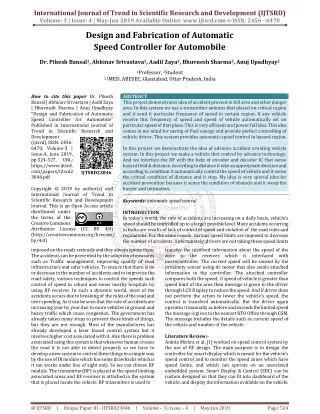
This paper describes about the design and fabrication of automatic drain cleaner. There are a large number of machines used for removing out the wastes from drains. Nowadays, automation plays a vital role in all industrial applications. The automatic drain cleaner can be used in domestic, industry, large plants, irrigation and drainage cleaning system. In order to overcome the problems in manual drain cleaning, Automatic Drain Cleaning System is implemented to clean and control the drainage level. Every automatic drain cleaner has four main components, namely DC motor, 12 V battery, chain drives and shafts. The rotational speed of the drive shaft is 26 rpm. But in this paper, only shaft design is calculated. The required power from a motor to drive this shaft is 60 W. In designing shaft, chain tension, sprocket load and bearing load are taken into account and also bending moment and torque are included. Ma Yi Yi Khin | Mg Aung Myo San Hlaing | Ma Myat Win Khaing "Design and Fabrication of Automatic Drain Cleaner" Published in International Journal of Trend in Scientific Research and Development (ijtsrd), ISSN: 2456-6470, Volume-3 | Issue-5 , August 2019, URL: https://www.ijtsrd.com/papers/ijtsrd27869.pdf Paper URL: https://www.ijtsrd.com/engineering/mechanical-engineering/27869/design-and-fabrication-of-automatic-drain-cleaner/ma-yi-yi-khin<br>

E N D
International Journal of Trend in Scientific Research and Development (IJTSRD) Volume 3 Issue 5, August 2019 Available Online: www.ijtsrd.com e-ISSN: 2456 – 6470 Design and Fabrication of Automatic Drain Cleaner Ma Yi Yi Khin1, Mg Aung Myo San Hlaing2, Ma Myat Win Khaing2 1Assistant Lecturer, 2Lecturer 1Department of Mechanical Engineering, Technological University, Mandalay, Myanmar 2Department of Mechanical Engineering, Technological University, Taunggyi, Myanmar How to cite this paper: Ma Yi Yi Khin | Mg Aung Myo San Hlaing | Ma Myat Win Khaing "Design and Fabrication of Automatic Drain Cleaner" Published in International Journal of Trend in Scientific Research and Development (ijtsrd), ISSN: 2456-6470, Volume-3 | Issue-5, August 2019, pp.1961-1966, https://doi.org/10.31142/ijtsrd27869 Copyright © 2019 by author(s) and International Journal of Trend in Scientific Research and Development Journal. This is an Open Access article distributed under the terms of the Creative Commons Attribution License (CC (http://creativecommons.org/licenses/by /4.0) Our proposed system is used to clean and control the drainage level using auto mechanism technique. Auto- mechanism is the major controlling unit and the drainage level a monitor by municipal. In this system hand wheel, chain, driver, bucket, and frame are used. The waste and gases produced from the industries are very harmful to human beings and to the environment, waste like bottles, etc. Floating in drain is lifted by teeth which are connected to chain. These administration strategies for a scope of hardware for overseeing and controlling amphibian vegetation is being used today, intended for particular plant sorts and for operation in particular sea-going environments. The device is placed across the drain so that only water flows through lower grids. Floating in drain is lifted by teeth which are connected to chain. This chain is attached to gears driven by motor. When the motor runs, the chain starts to circulate making teeth to lift up. The waste materials are lifted by teeth and are stored in waste storage tank. DC motor plays a major role in many applications; dc motor is required to be rotated in clockwise and counter clockwise directions. II. Types of Automatic Drain Cleaner Two types of Automatic Drain Cleaner are as follows: A.Automatic Drainage Cleaning System by using Solar Panel and B.Automatic Drainage Cleaning System by using Simple Formed. ABSTRACT This paper describes about the design and fabrication of automatic drain cleaner. There are a large number of machines used for removing out the wastes from drains. Nowadays, automation plays a vital role in all industrial applications. The automatic drain cleaner can be used in domestic, industry, large plants, irrigation and drainage cleaning system. In order to overcome the problems in manual drain cleaning, Automatic Drain Cleaning System is implemented to clean and control the drainage level. Every automatic drain cleaner has four main components, namely; DC motor, 12 V battery, chain drives and shafts. The rotational speed of the drive shaft is 26 rpm. But in this paper, only shaft design is calculated. The required power from a motor to drive this shaft is 60 W. In designing shaft, chain tension, sprocket load and bearing load are taken into account and also bending moment and torque are included. KEYWORDS: Automatic Drain Cleaner, Bending Moment, Chain Drives, Shaft. I. INTRODUCTION Automatic Drain Cleaner overcomes all sorts of drainage problems and promotes blockage free drains promoting continuous flow of drain water. In the modern area there have been adequate sewage problems where sewage water needs to be segregated to clean our surrounding environment. IJTSRD27869 BY 4.0) A design, “Automatic Drain Cleaning System” is implemented to use in an efficient way to control the disposal of wastages as shown in Figure 1. With regular filtration of wastages, clearance of gaseous substance is treated separately and monitors the disposal in frequent manner. Figure1. Automatic Drain Cleaner Every dynamic spring is subject to these constraints where variation of forces and alignment take place, to find a solution for the problem of water logging due to plastic, metal, others, and to treat problems like malaria, typhoid, etc. caused due to water accumulation. It can be said that major factors that affect the strength of the machine are design parameters, material selection, raw material defect, and surface imperfection. It is seen that design parameters i.e. operating modes, operating temperature, and imperfections. @ IJTSRD | Unique Paper ID – IJTSRD27869 | Volume – 3 | Issue – 5 | July - August 2019 Page 1961
International Journal of Trend in Scientific Research and Development (IJTSRD) @ www.ijtsrd.com eISSN: 2456-6470 III. The main components of “Automatic Drain Cleaner” have been developed. They are: A.DC Motor B.Sprockets C.Bearings D.Chain Drivers E.Shaft F.Sheet Metal and G.Bucket. Sprockets A sprocket or sprocket wheel is a profiled wheel with teeth, or cogs, that mesh with a chain; track or other perforated or indented material as shown in Figure 2. The name sprocket” applies generally to any wheel upon which radial projections engage a chain passing over it. Components of Automatic Drain Cleaner Figure 3. Chain Drive Shaft A shaft is a rotating machine element, usually circular in cross section, which is used to transmit power from one part to another, or form a machine which produces power to a machine which absorbs power as shown in Figure 4. The various members such as pulleys and gears are mounted on it. Figure4. Spline Shaft IV. A.The automated mechanism is basically designed to filter out this solid waste of the running drains and hence removing the possibility of any blockage of the flowing waste water. B.The turbine is the power generating element that functions on the hydraulic power and hence then drive the chain mechanism. C.The chain mechanism is being fitted with the wire mesh filter that just picks up the solid waste while the liquid waste flows through the mesh. D.The size of mesh holes can be adjusted in order to decide the different size of solid waste we are working on. E.The system is being adjusted at a angle so that mesh is able to hold the solid waste. F.The storage box is kept where the solid waste is collected and later that box can be cleaned to remove the collected waste. V. Design Theory Design of the Shaft Theshaft must have adequate torsional strength to transmit torque and not be over stressed. Shafts are mounted in bearings and transmit power through devices such as sprockets and chains. Components such as sprockets are mounted on shafts using keys. Shaft must sustain a combination of bending and torsional loads. A shaft is a rotating machine element which is used to transmit power from one place to another. The power is delivered to the shaft by some tangential force and the resultant torque set up within the shaft permits the power to be transferred to various machines linked up to the shaft. In designing shaft on the basic of strength, the following cases may be considered: Working of Automatic Drain Cleaner Figure2. Sprocket It is distinguished from a gear in that sprockets are never meshed together directly, and differs from a pulley in that sprockets have teeth and pulleys are smooth. Sprockets are used in bicycles, motorcycles, cars, tracked vehicles, and other machinery to transmit rotary motion between two shafts where gears are unsuitable or to impart linear motion to a track, tape etc. Chain Drive Chain drive is a way of transmitting mechanical power from one place to another. It is often used to convey power to the wheels of a vehicle, particularly bicycles and motorcycles. It is also used in a wide variety of machines besides vehicles. Most often, the power is conveyed by a roller chain, known as the drive chain or transmission chain, passing over a sprocket gear, with the teeth of the gear meshing with the holes in the links of the chain. The gear is turned, and this pulls the chain putting mechanical force into the system as shown in Figure 3. Another type of drive chain is the Morse chain. This has inverted teeth. Sometimes the power is output by simply rotating the chain, which can be used to lift or drag objects. In other situations, a second gear is placed and the power is recovered by attaching shafts or hubs to this gear. Though drive chains are often simple oval loops, they can also go around corners by placing more than two gears along the chain; gears that do not put power into the system or transmit it out are generally known as idler-wheel. By varying the diameter of the input and output gears with respect to each other, the gear ratio can be altered. @ IJTSRD | Unique Paper ID – IJTSRD27869 | Volume – 3 | Issue – 5 | July - August 2019 Page 1962
International Journal of Trend in Scientific Research and Development (IJTSRD) @ www.ijtsrd.com eISSN: 2456-6470 A.Shaft subjected to twisting moment or torque only B.Shaft subjected to bending moment only C.Shaft subjected to combined twisting and bending moments D.Shaft subjected to axial loads in addition to combined torsional and bending loads. Work Done and Power, Work done per minute = (Force) (Distance) =(Average) (Angular displacement) N π 2 T 2 Where, 106p (in Newton) per mm width of chain for silent chains Rated W (in Newton) for roller chains W 106p B power velocity line Pitch Service Factor, K S 8 K K K 1 2 3 Where, K service factor S factor = 1 K load 60 1 lubrication factor K 2 Where, T = torque of motor N = number of speed (rpm) Sprocket Load on the Shaft 2 T K Power Transmitted, W P rating factor 3 v θ B 9 p = D sin n K S 180 Where, v = speed of the chain n = factor of safety K = the service factor Tangential Driving Force, Power tran T W = breaking work B = 2 Dsin Where, p = pitch T = number of teeth Centrifugal Tension in the Chain 2 C v m F (Newton) Where, C F = centrifugal tension m = total mass on the chain v = speed of the chain Chain Length, p K L S smitted (inwatts) P ` 3 10 F Speed of chain in m/s v Equivalent Twisting Moment (e M m K e T T ) 2 2 K T t 11 4 Where, e K = shock factors K = combined fatigue M = maximum bending moment T = torque of motor Diameter of the Shaft, 3 d τ 16 T = equipment twisting moment 2 m T T T T 2x p 1 2 2 1 5 K 2 p 2π x t Where, L = the length of the chain K = number of chain links p = pitch x = the center distance T = number of teeth Tension in Chain due to Sagging, x mg k FS (Newton) Where, m = mass of the chain in kg per meter length x = center distance in meters k= constant which takes into account the arrangement of chain drive = 2 to 6, when the center line of the chain in inclined to the horizontal at an angle less than = 1 to 1.5, when the center line of the chain in inclined to the horizontal at an angle greater than Factor of Safety, W n safety, of Factor π 12 T e T = equivalent twisting moment Where, τ = maximum shear stress d = shaft diameter Angle of Twist, 6 e TL Angle of twist, 13 θ GJ Where,θ = the angle of twist (Degree) T = the applied torque (Nm) L = shaft length (m) 40 40 4 J = polar moment on inertia of shaft cross section ( m ) 2 G =shear modulus of elasticity of shaft ( N/m ) B 7 4 π d W J = Polar movement of inertia = 32 d = diameter of shaft @ IJTSRD | Unique Paper ID – IJTSRD27869 | Volume – 3 | Issue – 5 | July - August 2019 Page 1963
International Journal of Trend in Scientific Research and Development (IJTSRD) International Journal of Trend in Scientific Research and Development (IJTSRD) @ www.ijtsr www.ijtsrd.com eISSN: 2456-6470 Power Transmitted by a Belt Power transmitted between a belt and a pulley is expressed as the product of difference of tension and belt velocity. P = (T1 - T2) v Where, P=Power transmitted by belt T1=Tension in the tight side T2=Tension in the slack side v=Velocity of the belt in m/s Power, Electrical power is the rate at which electrical energy is converted to another from, such as motion, heat, or an electromagnetic field. The common symbol for power is the uppercase letter P, the standard unit is the W symbolized by W. T N 2π a Belt Angle of Deflection, 584M θ L Power transmitted between a belt and a pulley is expressed as the product of difference of tension and belt velocity. t 14 4 Gd (Same direction) 21 θ θ θ 1 2 P=Power transmitted by belt =Tension in the tight side =Tension in the slack side v=Velocity of the belt in m/s (Different direction) θ Where, L = shaft length (m) G = shear modulus of elasticity of shaft ( N/m d = diameter of shaft T θ θ 1 2 M = Torque (Nm) t 2 N/m ) Electrical power is the rate at which electrical energy is converted to another from, such as motion, heat, or an electromagnetic field. The common symbol for power is the uppercase letter P, the standard unit is the WATT, 1 σ = 15 bt Where, σ = Stress of belt T1 = Tension in tight side B = Width of belt t =Thickness of belt Length of Open Belt Drive, An open belt drive is used to rotate the driven pulley in the same direction of driving pulley. The length of belt can be calculate by the following equation. ) r (r 2 P = 22 60 T = F × r v 23 60 N = 24 πd Where, P =Power (kW) N=Drive pulley rpm T=Torque (Nm) r=Pulley radius (m) v=Velocity of belt (m/s) d=Pulley diameter (m) Relationship between Centripetal Force and Gravity force, mv2 An open belt drive is used to rotate the driven pulley in the same direction of driving pulley. The length of belt can be 1 2 L = π(r1+r2)+2x+ 16 x Where,r1 and r2 =Radii of the larger and smaller pulleys x =Distance between the centers of two pulleys L =Total length of the belt Maximum Tension in the Belt, The maximum tension in the belt is equal to the total in the tight side of the belt. T= Maximum stress × Cross section area of the belt T= σ × b × t When, Centrifugal tension is considered, T = T1+TC Where, σ =Maximum safe stress B =Width of the belt t =Thickness of the belt T1=Tension in the tight side T = Maximum tension in the belt Centrifugal Tension, The tension caused by centrifugal force is called centrifugal tension. FC = mv2 Where, FC=Centrifugal tension m=Mass of belt per unit length in kg v=Linear velocity of belt in m/s Ratio of Driving Tension for Flat Belt Drive, T =eμθ =Radii of the larger and smaller pulleys x =Distance between the centers of two pulleys Centripetal Force and Gravity force, FC= 25 r Fg= mg Where, FC=Centripetal force Fg=Gravity force m=Material mass in the bucket v =belt velocity in m/s g =Gravity acceleration, 9.81 m/s VI. Result for Specification By using the following specifications, the shaft design of automatic drain cleaner can be calculated. Detailed drawing of automatic drain cleaner is shown in Figure 5. of automatic drain cleaner is shown in Figure 5. 26 The maximum tension in the belt is equal to the total tension =Centripetal force T= Maximum stress × Cross section area of the belt m=Material mass in the bucket v =belt velocity in m/s g =Gravity acceleration, 9.81 m/s2 17 18 for Automatic Automatic Drain Cleaner By using the following specifications, the shaft design of automatic drain cleaner can be calculated. Detailed drawing The tension caused by centrifugal force is called centrifugal 19 Ratio of Driving Tension for Flat Belt Drive, 1 20 T Where, T1=Tension in the tight side T2=Tension in the slack side µ=Coefficient of friction between belt and pulley of contact 2 µ=Coefficient of friction between belt and pulley θ=Angle Figure5. Detail Drawing of Automatic Drain Cleaner 5. Detail Drawing of Automatic Drain Cleaner @ IJTSRD | Unique Paper ID – IJTSRD27869 27869 | Volume – 3 | Issue – 5 | July - August 2019 August 2019 Page 1964
International Journal of Trend in Scientific Research and Development (IJTSRD) @ www.ijtsrd.com eISSN: 2456-6470 L = Kp T 1 Power = 60 W Sprocket Diameter = 0.04 m Rpm = 26(Motor) 45 α (Sprocket) PQ = 0.722 m (Total Length) PB =CD = 0.045 m BC = 0.577 m DQ = 0.055 m m = 1 kg m = 5 kg m = 2 kg Motor Load on the Shaft, For Motor Q, 60 P T Q 60 60 = 22.037 Nm Own weight of Motor, m = 2 kg W = mg = 29.81 = 19.62 N Sprocket Load on the Shaft, For sprocket B and C (same diameter), Number of teeth, T = 14 D = 40 mm 2 = 9 mm Centrifugal tension in the chain, 2 mv FC T 14 2 2 T T T T 2x p 1 2 2 1 K = 2 p 2π x 14 14 2 914.4 = bucket 2 9 waste = 217.2 L = 217.29 = 1954.8 mm Chain mass, chain 2 m = Q 3 1954.8 10 2π N = 1.023 kg/m k FS SF = 11.0239.81914.4 = 9.177 N Power transmitted, 2 106p B Factor of safety, W = m g x 2π 26 10 3 W Q B n = W 60 = 0.054 = 1111.111 N θ p = D sin r πDN v (Same diameter) 60 3 π 40 10 26 = 60 = 0.054 m/s m m m = 3(1) = 3 kg bucket = 2(5) = 10 kg waste = 2(2) = 4 kg chain m = m m m waste bucket chain 2 8.5(0.054) C F = 3 20 10 = 1.239 N Chain Load on the Shaft, Tension in Chain due to sagging, Centre distance, x = 914.4 mm Chain mass, m = 2 kg Figure6.Bending Moment Diagram @ IJTSRD | Unique Paper ID – IJTSRD27869 | Volume – 3 | Issue – 5 | July - August 2019 Page 1965
International Journal of Trend in Scientific Research and Development (IJTSRD) @ www.ijtsrd.com eISSN: 2456-6470 channel is 1feet and height of the channel is 3feet, rate of disposal of waste is considered as uniform, lifter speed and motor speed is also constant. In design calculation of shaft, the length is 0.722 m and storage tank area is 0.2 m . The torque required to rotate the shaft is 22.04 Nm and maximum bending moment due to the load exerted on the shaft is 27.08 Nm. Then, the design diameter 19 mm is obtained. Besides, the angle of twist and the angle of deflection are also calculated in this paper. VIII. REFERENCES [1]Author A: Ganesh Rampur,Assistant Professor, Mechanical Department, PESITM, Shimoga, Karnataka, India No. 1 2 3 4 5 6 7 8 9 10 11 12 Table1. The Calculated Result for Automatic Drain Cleaner Calculate data of parts Own weight of motor Result 19.62 9 1.239 9.177 592.593 Unit N mm N N N N Nm Nm Nm m Degree Degree Pitch Centrifugal tension Sagging tension Tangential force Total load acting on sprocket 603.009 Resultant B.M at C Resultant B.M at D Equivalent twisting moment Shaft diameter Angle of Twist Angle of Deflection 2 26.434 24.619 46.218 0.019 0.016 0.294 U, Author B: Vinod V [2]R. S. KHURMI and J. K. GUPTA, 2005, ‘Machine Design’, 1st edition, EURASIA ISHING HOUSE (PVT.) Ltd. [3]<http://en.wikipedia.org/wiki/Drain_cleaner> VII. In this paper, the design of shaft for drainage cleaning system is calculated. Automatic Drain Cleaner is simple and easy to construct. The Automatic Drain Cleaner is widely used in domestic and industry in every country all over the world. Designing Automatic Drain Cleaner consists of four main components such as DC motor, 12 V battery, chain drivers and shafts. The motor is 60 W DC motor. The mild steel is used for shaft material in this thesis. Depth of the Discussions and Conclusion [4]http://esatjournals.net/ijret/2016v05/i07/IJRET2016 0507043.pdf [5]http://esatjournals.net/ijret/2016v05/i07/IJRET2016 0507043.pdf [6]www.internationaljournalssrg.org/IJIE/2016/Special- Issuse/.../IJIE-ICEIET- P119.pdf> [7]7<www.madehow.com>Volume 7> @ IJTSRD | Unique Paper ID – IJTSRD27869 | Volume – 3 | Issue – 5 | July - August 2019 Page 1966