Download
1 / 5
50 likes | 109 Vues
In this thesis, design calculation and fabrication of H Darrieus VAWT are carried out. The purpose of this thesis is to produce power of electricity. H Darrieus wind turbine is a type of vertical axis wind turbine. This wind turbine consists of three straight blades, technically an airfoil which is connected to the radial arm and rotating main shaft. In this thesis, the components required for this wind turbine like airfoil, main shaft and bearing are properly designed. The power calculation with respect to the wind velocity, swept area and number of blades are included. The yearly average wind velocity is 4 m s and number of blade is three. The diameter of rotor is 0.915 m and height of rotor is 1.067 m. As a result, the turbine power is 14.16 W. The NACA 0015 airfoil of NACA series is chosen. 100000 in Reynolds number, 37.5 in the ratio of lift and drag coefficient and 6u00c2u00b0 in angle of attack are included in this airfoil. The rotor solidity is 60 percentages, the chord length of airfoil is 0.2 m and maximum thickness of airfoil is 30 percentages of chord length. Finally, the components of H Darrieus vertical axis wind turbine are fabricated with zinc sheet, commercial steel, cast iron, and all parts are assembled together after manufacturing of these components. Hnin Yu Yu Kyaw | Ei Cho Cho Theik | Khaing Zar Nyunt "Design and Fabrication of H-Darrieous VAWT" Published in International Journal of Trend in Scientific Research and Development (ijtsrd), ISSN: 2456-6470, Volume-3 | Issue-4 , June 2019, URL: https://www.ijtsrd.com/papers/ijtsrd25159.pdf Paper URL: https://www.ijtsrd.com/engineering/mechanical-engineering/25159/design-and-fabrication-of-h-darrieous-vawt/hnin-yu-yu-kyaw<br>

E N D
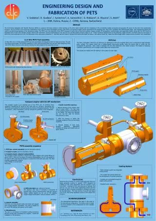
International Journal of Trend in Scientific Research and Development (IJTSRD) Volume: 3 | Issue: 4 | May-Jun 2019 Available Online: www.ijtsrd.com e-ISSN: 2456 - 6470 Design and Fabrication of H-Darrieous VAWT Hnin Yu Yu Kyaw, Ei Cho Cho Theik, Khaing Zar Nyunt Department of Mechanical Engineering, Technological University, Toungoo, Myanmar How to cite this paper: Hnin Yu Yu Kyaw | Ei Cho Cho Theik | Khaing Zar Nyunt "Design and Fabrication of H- Darrieous VAWT" Published in International Journal of Trend in Scientific Research and Development (ijtsrd), ISSN: 2456- 6470, Volume-3 | Issue-4, June 2019, pp.1570-1574, URL: https://www.ijtsrd.c om/papers/ijtsrd25 159.pdf Copyright © 2019 by author(s) and International Journal of Trend in Scientific Research and Development Journal. This is an Open Access article distributed under the terms of the Creative Commons Attribution License (CC BY 4.0) (http://creativecommons.org/licenses/ by/4.0) (sunshine) energy, where ‘repetitive’ refers to the 24 hours major period. Note that the energy is already passing through the environment as a current or flow, irrespective of there being a device to intercept and harness this power. Such energy may also be called Green Energy or Sustainable Energy. There are five types of Renewable Energy. They are Wind Energy, Solar Energy, Hydro Power, Biomass and Geothermal. Renewable Energy often provides energy in four important areas: electricity generation, air and water heating or cooling, transportation and rural (off-grid) energy services The VAWT offers some distinct advantages relative to HAWT, including easy installation and maintenance, low noise, and potentially simple blade design. The H-DARRIEUS VAWT blade design is simple to construct, but its needs stronger blades. There are two principal types of VAWT rotor, lift-type and drag-type. Drag type rotors work by having greater drag on one side of the rotor axis than the other. A well-known example of this type of rotor is a cup anemometer. Drag type rotors are very simple, but the high drag on the half of the rotor which is travelling upstream limits their efficiency. In addition, the rotors experience a high level of thrust in the wind direction, which limits their maximum size. Wind turbines generally consist of two basic types with the classification being based on the orientation of the axis of the rotor. The main classifications are VAWT and HAWT. ABSTRACT In this thesis, design calculation and fabrication of H-Darrieus VAWT are carried out. The purpose of this thesis is to produce power of electricity. H-Darrieus wind turbine is a type of vertical axis wind turbine. This wind turbine consists of three straight blades, technically an airfoil which is connected to the radial arm and rotating main shaft. In this thesis, the components required for this wind turbine like airfoil, main shaft and bearing are properly designed. The power calculation with respect to the wind velocity, swept area and number of blades are included. The yearly average wind velocity is 4 m/s and number of blade is three. The diameter of rotor is 0.915 m and height of rotor is 1.067 m. As a result, the turbine power is 14.16 W. The NACA 0015 airfoil of NACA series is chosen. 100000 in Reynolds number, 37.5 in the ratio of lift and drag coefficient and 6° in angle of attack are included in this airfoil. The rotor solidity is 60 percentages, the chord length of airfoil is 0.2 m and maximum thickness of airfoil is 30 percentages of chord length. Finally, the components of H-Darrieus vertical axis wind turbine are fabricated with zinc sheet, commercial steel, cast iron, and all parts are assembled together after manufacturing of these components. Keywords: Blade, Airfoil, Material Selection, Shaf, Angle of attack, Lift Force, Drag Force I. INTRODUCTION Renewable Energy means energy obtained from natural and persistent flows of energy occurring in the immediate environment. An obvious example is solar IJTSRD25159 The two most common types of VAWTs are the Darrieus and Savonius configurations. Darrieus wind turbines have lift- based airfoils around a rotating shaft while Savonius turbines have drag-based “scoops” around a rotating axis. Due to the higher efficiency and lower weight of the Darrieus configuration, it was chosen over the Savonius counterpart for the preliminary design. The Darrieus wind turbine has several sub-configurations including the full-Darrieus (or eggbeater), the “H” and the “V” configurations. This has blades which are arranged on the vertical axis and are rotated by wind and therefore it doesn’t require a yaw mechanism since it can harness wind from any direction. In this paper, the design and fabrication of H-DARRIEUS VAWT is compared by theoretical and actual results. .H- Darrieus VAWT requirements are discussed and the main types of VAWT are described. II. H-DARRIEUS VAWT A.Working Principle of H-Darrieus VAWT The type of airfoils that have been studied for H- the length between leading edge and trailing edge of the blade profile. The blade thickness and shape is determined by the airfoil used, in this case it will be a NACA airfoil, where the blade curvature and maximum thickness are defined as percentage of the chord. H-DARRIEUS VAWT is constructed six components. They are blades, shaft, radial arms, bearing, screws and support. @ IJTSRD | Unique Paper ID – IJTSRD25159 | Volume – 3 | Issue – 4 | May-Jun 2019 Page: 1570
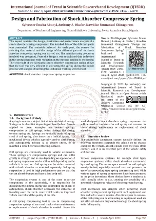
International Journal of Trend in Scientific Research and Development (IJTSRD) @ www.ijtsrd.com eISSN: 2456-6470 the turbine blades, the material selection was completed using stress analysis, Classical Lamination Theory and Finite Element Analysis based on the required stresses that will be applied by lift, drag and centripetal forces.It was determined that the material should have the following attributes: Suitable strength to weight ratio, Rigid, Able to withstand calculated shear and normal stresses, Weather resistant, Fatigue resistant,Will not cause galvanic corrosion on struts and Smooth surface finish for aerodynamic purposes . Materials that considered were zinc alloy, steel and aluminum. Steel can be immediately rejected due to weight. Aluminum would satisfy the weight requirement, but exhibits poor fatigue resistance. For this reason, the decision was made to use a zinc alloy material for blades and airfoils. Cast iron is chosen to construct for radial arms and support frame. Cast irons are used in wide variety of application owing to the properties like good fluidity, ease of casting, low shrinkage, excellent machinability, wear resistance and damping capacity. The material that has been chosen for shaft is mild-steel due to its high strength properties that highly suits the requirements of the wind turbine. While working on a low budget, mild steel proves to be the best. It is an ideal material that keeps construction cost as low as possible. Mild steel is relatively cheaper than other metals. III. DESIGN THEORY OF VAWT A.Selection of Airfoil Before starting the design of H-Darrieus VAWT, selection of Blade airfoil is firstly considered. In this H-Darrieus VAWT, the NACA 0015 airfoil of NACA series is chosen. 100000 in Reynolds number, 37.5 in the ratio of lift and drag coefficient and 6° in angle of attack are included in this airfoil. The formula for the shape of a NACAs 0015 foil, with “15” being replaced by the percentage of thickness to chord is; − − = 3516 . 0 1260 . 0 2969 . 0 c c c Figure1. Main components of H-Darrieus VAWT The type of airfoils that have been studied for H-Darrieus VAWT is a four digit NACA wing section. In this type of NACA airfoil, the first digit describing maximum camber as percentage of the chord, the second digit describing the distance of maximum camber as from the airfoil leading edge in tens of percent of the chord and the last two describing maximum thickness of the airfoil as percent of the chord. Shaft is a rotating machine element which is used to transmit power from one place to another. The power is delivered to the shaft by some tangential force and the resultant torque set up within the shaft permits the power to be transferred to various machines linked up to the shaft. In order to transfer the power from one shaft to another, the various members such as pulleys, gears etc. are mounted on it. These members along with the forces exerted upon them causes the shaft to rotate. The distance between center shaft and the air foil is called radial arm. Specific systems are needed to be installed for easy assembling and dismantling of airfoil and shaft. The material used for fabrication of radial arms is aluminum because of its light weight and high strength. A bearing is a mechanical device that supports the moving parts of a machine and to guide or confine its motion, while preventing motion in the direction of applied load. Its primary purpose is to reduce friction with a minimum loss of energy and at the same time should control the rate of wear. Besides, its purpose is to support a load while permitting relative motion between two elements of a machine. The most common type of bearing support is a rotating shaft, resisting purely radial loads or a combination of radial and axial (thrust) load. When the mechanical equipment positions are changed that should be balanced, stability and balance are important. Therefore, supports are used due to torque changing of blades while rotating. Wind turbine motion can result in a fatigue stress over the support part. A screw, or bolt are types of fasteners that characterized by a helical ridge, defined as an external thread or thread- wrapped around a cylinder. Some screw threads are designed to mate with a complementary thread, known as an internal thread. B.Material Selection For structural design it is important to consider all materials appropriate to the application. For the design of this turbine, the material should be cost effective and capable of providing the required properties for each application. For 2 3 4 t x x x x x + − . 0 2843 . 0 1015 Y c c c c = the chord length, x = the position along the chord from 0 to c, y = the half thickness at a given value of x t = the maximum thickness as a fraction of the chord B.Determination of Wind Turbine Design Parameters The distance between center shaft and the air foil is called radial arm. Specific systems are needed to be installed for easy assembling and dismantling of airfoil and shaft. The material used for fabrication of radial arms is aluminum because of its light weight and high strength. A bearing is a mechanical device that supports the moving parts of a machine and to guide or confine its motion, while preventing motion in the direction of applied load. Its primary purpose is to reduce friction with a minimum loss of energy and at the same time should control the rate of wear. Besides, its purpose is to support a load while permitting relative motion between two elements of a machine. The most common type of bearing support is a rotating shaft, resisting purely radial loads or a combination of radial and axial (thrust) load. The used formula is P = X V Fr + Y Fa Where, P = Equivalent dynamic load, N, Fr = Radial load on bearing, N, Fa = Axial load on bearing, N, @ IJTSRD | Unique Paper ID – IJTSRD25159 | Volume – 3 | Issue – 4 | May-Jun 2019 Page: 1571
International Journal of Trend in Scientific Research and Development (IJTSRD) @ www.ijtsrd.com eISSN: 2456-6470 X = Radial load factor Y = Axial load factor V = Rotation factor The swept area is the section of air that encloses the turbine in its movement, the shape of the swept area depends on the rotor configuration, this way the swept area of an HAWT is circular shaped while for a straight-bladed vertical axis wind turbine the swept area has a rectangular shape and is calculated using: A = D × H where, A = Swept area, D = Rotor diameter, H = Rotor height The swept area limits the volume of air passing by the turbine. The rotor converts the energy contained in the wind in rotational movement so as bigger the area, bigger power output in the same wind conditions. The power available from wind for a vertical axis wind turbine can be found from the following formula. 1 AV Pw ρ = blade’s leading edge inside the circumference described by the blade path. IV. Aerodynamics Theory The aerodynamic analysis of vertical axis wind turbines is complicated due to their orientation in the oncoming wind. The vertical axis wind turbines have a rotational axis perpendicular to the oncoming airflow. This accounts for aerodynamics that is more complicated than a conventional horizontal axis wind turbine. A.Lift Force The lift force is one of the major force components exerted on an airfoil section inserted in a moving fluid.It acts normal to the fluid flow direction. This force is a consequence of the uneven pressure distribution between the upper and lower blade surfaces and can be expressed as follow: 1ρ = 3 F AV C l l 2 where, ρ = the air density, Cl = the lift coefficient, A = the blade airfoil area B.Drag Force The drag force, D acts in the direction of the fluid flow. Drag occurs due to the viscous friction forces on the airfoil surfaces, and the unequal pressure on surfaces of the airfoil. Drag is a function of the relative wind velocity at the rotor surface, which is the difference between the wind speed and the speed of the surface, and can be expressed as; 1ρ = 3 2 where, Pw= the output power [W], v = the velocity of the wind [m/s], ρ = the air density [kg/m3], A= swept area [m2] Reference density used its standard sea level value (1.225 kg/m3 at 15ºC). The power of the turbine takes from wind is calculated using the power coefficient: Cp =Captured mechanical power by blade/ available power in wind The power coefficient is strongly dependent on tip speed ratio, defined as the ratio between the tangential speeds at the actual wind speed. Rω λ = 2 N Π = ω where, ? = tip-speed-ratio, ω = angular velocity [rad/s], R = rotor radius [m], vo = ambient wind speed [m/s], N = number of revolution [rpm] The chord is the length between leading edge and trailing edge of the blade profile. The blade thickness and shape is determined by the airfoil used, in this case it will be a NACA airfoil, where the blade curvature and maximum thickness are defined as percentage of the chord. The number of blades has a direct effect in the smoothness of rotor operation as they can compensate cycled aerodynamic loads. The solidity σ is defined as the ratio between the total blade area and the projected turbine area. The initial angle of attack is the angle the blade has regarding its trajectory, considering negative the angle that locates the 3 F AV C D d 2 where, ρ = the air density, Cd = the drag coefficient, A = the blade airfoil area C.Reynolds Number The Reynolds number Re is the ratio of the inertia forces to the viscous forces. The Reynolds Number is calculated as follow: ρ µ v µ υ = =kinematics viscosity 0v ρ ϑC v UL UL = = = RE µ 60 Where, ρ L= the characteristics length scale C= blade chord length Vθ = blade tip velocity D.Betz Number The Betz number or Betz limit is a useful performance indicator of wind turbines. It is the maximum amount of power that can be extracted by a wind generator from the available wind kinetic energy. This maximum turbine power is the difference between the upstream and downstream wind powers. ( 2 dt where, PT = turbine output power (W), vu= upstream wind velocity (m/s), vo= downstream wind velocity (m/s) ) 1 dm 2 2 = − P v v T u o @ IJTSRD | Unique Paper ID – IJTSRD25159 | Volume – 3 | Issue – 4 | May-Jun 2019 Page: 1572
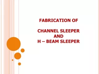
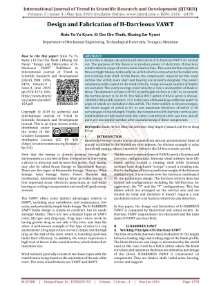
International Journal of Trend in Scientific Research and Development (IJTSRD) @ www.ijtsrd.com eISSN: 2456-6470 E.Theory of Vertical Shaft Diameter In this case, the forces subjected on the shaft are considered. One of the blade loads, centrifugal force is also a fact firstly considered. Centrifugal force is used to design the structural members of each blade. The formula for centrifugal force pulling a blade away from the rotor hub is WxSRxv CF 81 . 9 where, W = the weight of the blade in kg SR = the speed ratio at the blade center of gravity RC = distance in meter from the rotational to the blade center of gravity The formula for shaft torque is RxP Toque = Table3. Airfoil Coordinates for H-Darrieous VAWT X Y(upper) Y(lower) 0.2 0.00013 0.19 0.00078 0.18 0.00144 0.17 0.0021 0.16 0.00264 0.15 0.00318 0.14 0.00366 0.13 0.00408 0.12 0.00498 0.11 0.00528 0.10 0.00552 0.09 0.00582 0.08 0.00594 0.07 0.00599 0.06 0.00594 0.05 0.00557 0.04 0.00533 0.03 0.00473 0.02 0.00354 0.01 0 Table4. Selection of Bearing Number Principal Dimensions (mm) Rating (N) d D B C 25 73 7 3120 0.00013 0.00078 0.00144 0.0021 0.00264 0.00318 0.00366 0.00408 0.00498 0.00528 0.00552 0.00582 0.00594 0.00599 0.00594 0.00557 0.00533 0.00473 0.0354 0 = xRC vXTSR Where, R = rotor radius (m) P = rotor power (Watt) TSR = tip speed ratio The required shaft diameter, T x D π F.Input Data In this thesis required data are followed, H-Darrieous VAWT,Rotor diameter, D =0.915 Rotor Height, H =1.067 Average wind speed, v=4(m/s)(At TU Toungoo) Air density, ρα =1.225kg/m3 No. of blade, n=3 Tip-speed-ratio, σ=6 Reynold’s number, Re=100,000 Angle of attack, α =6˚ Lift- coefficient, Cl = 0.75441 Drag-coefficient, Cd =0.02012 Maximum Cl/Cd =37.5 V. RESULT DATA Table1. Dimensions of the shaft No Description 1 Diameter of shaft 2 Length of shaft Table2. Dimensions of radial arm Sr. No. 1 Number of arms 2 = 2 Basic Load Bearing Number s S Co 1960 61805 Table5. Result Table of Theoretical and Actual Output Power at Various Wind Speeds Wind Speed, (m/s) 2.5 rpm (Theoretical) 52 rpm (Actual) 48 3 62 55 3.5 73 67 4 83 74 4.5 94 86 Dimension 0.03m 1.524m DESCRIPTION DIMENTION Figure2. Calculation of Theoretical and Actual Output Power at Various Wind Speeds Table 6, Illustrate the variation of theoretical and actual output power at various wind speed from 2.5 m/s to 4.5 m/s. Results for theoretical and actual output power are nearly equivalent at wind speed 2.5 m/s to 3.5 m/s. But wind speed 4 m/s and 4.5 m/s, the theoretical output power is slightly higher than the actual output power. Table 4.3 shows the results of theoretical and actual output power at various wind speed. 3 2 Arm length 0.381m 3 Center disc diameter 0.152m 4 Center drill diameter 0.0254m 5 Side holes diameter slide holes position from the outer end Thickness 0.012m 6 0.0127m 7 0.003175m @ IJTSRD | Unique Paper ID – IJTSRD25159 | Volume – 3 | Issue – 4 | May-Jun 2019 Page: 1573
International Journal of Trend in Scientific Research and Development (IJTSRD) @ www.ijtsrd.com eISSN: 2456-6470 Table 6.Result Table of Theoretical and Actual rpm at Various Wind Speeds Wind Speed, (m/s) 2.5 rpm (Theoretical) 52 rpm (Actual) 48 result, the output power is 19.921 W at wind speed 4.5 m/s and 86 rpm. As a result, there was slightly different power output in theoretical and actual results. The power output from theoretical result is greater than actual power output. In this thesis, the blade design for H-Darrieus VAWT is mainly studied. In this thesis, designs for blade, airfoil, shaft and bearing are presented. In blade design, the airfoil coordinates and angle of attack plays a pivotal role. Acknowledgement The author would like to thank my parents for the best wish to join the matter course at DRI. The author greatly expresses her thanks to all persons whom concern to support in preparing this paper. References [1]Suliman Aleivi, Design and fabrication of a Giromill VAWT, Department of Mechanical Engineering, Eastern Mediterranean University, 2016. 3 62 55 3.5 73 67 4 83 74 4.5 94 86 [2]Tapan H.barot: A Review on Straight Bladed Vertical Axis H-type Darrieous Wind Turbine,2015. Figure3. Calculation of Theoretical and Actual rpm at Various Wind Speeds VI. Conclusion Firstly, it is important to understand of wind turbine which is related to wind speed. In this thesis, the most suitable blade profile is selected as NACA0015. The rotor diameter is 1 m and the available average wind speed is 4 m/s. The wind turbine converts from wind energy to electrical energy. In theoretical result, the output power is 5.97 W at wind speed 3 m/s and 62 rpm. According to the actual result, the output power is 5.863 W at wind speed 3 m/s and 55 rpm. In theoretical result, the output power is 14.16 W at wind speed 4 m/s and 83 rpm. According to the actual result, the output power is 13.964 W at wind speed 4m/s and 74 rpm. In theoretical result, the output power is 20.16 W at wind speed 4.5 m/s and 94 rpm. According to the actual [3]Louris Vathan.B: Design and Fabrication of Three Bladed Giromill Wind Turbine, April, 2014. [4]Jonathan Clarke: Design of a Vertical-Axis Wind Turbine, April, 2014. [5]Javier Castillo, Small-Scale VAWT Design, December, 2011. [6]Steven D.Miller: Lift, Drag and Moment of a NACA 0015 Airfoil Department of Aerospace Engineering, The Ohio State University, May, 2008, [7]Ira H. Abbott and Albert E. Von Doenhoff: Theory of Wing Sections, NASA, New York, 1949. @ IJTSRD | Unique Paper ID – IJTSRD25159 | Volume – 3 | Issue – 4 | May-Jun 2019 Page: 1574