Download
1 / 33
390 likes | 861 Vues
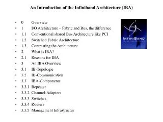
An Introduction of the Infiniband Architecture (IBA). 0 Overview 1 I/O Architecture – Fabric and Bus, the difference 1.1 Conventional shared Bus Architecture like PCI 1.2 Switched Fabric Architecture 1.3 Contrasting the Architecture 2 What is IBA? 2.1 Reasons for IBA 3 An IBA Overview

E N D
An Introduction of the Infiniband Architecture (IBA) • 0 Overview • 1 I/O Architecture – Fabric and Bus, the difference • 1.1 Conventional shared Bus Architecture like PCI • 1.2 Switched Fabric Architecture • 1.3 Contrasting the Architecture • 2 What is IBA? • 2.1 Reasons for IBA • 3 An IBA Overview • 3.1 IB-Topologie • 3.2 IB-Communication • 3.3 IBA-Components • 3.3.1 Repeater • 3.3.2 Channel-Adapters • 3.3.3 Switches • 3.3.4 Routers • 3.3.5 Management Infrastructur
An Introduction of the Infiniband Architecture (IBA) • 3.4 IB-Layers • 3.4.1 Physical-Layer • 3.4.2 Link Layer • 3.4.3 Network Layer • 3.4.4 Transport Layer • 4 IB-Market Appreciation • 4.1 First Vendors with IBA-Components • 4.2 Mellanox, a short representation • 4.2.1 Infinihost MT23108 • 4.2.2 Infinibridge MT21108 • 4.2.3 Infiniscale MT43132 • 5 Summary • 6 References
1.1 Conventional Bus Architecture • Some drawbacks of PCI: • - P2P-Bridge needs for more devices • - shared bandwith • uncontrolled termination • many pins for each connection • most disadvantage: can´t support „out of box“ CPU Systembus System Memory System Controller (System-to-I/O-Bridge) System-I/O Bus (PCI) #1 PCI to PCI Bridge PCI to PCI Bridge SCSI I/O Controller PCI-Bus#2 PCI-Bus#3 I/O Controller SCSI I/O Controller Grahic I/O Controller LAN I/O Controller
Some Words to PCI (1.1) The PCI bus was developed in the early 1990´s. Goal: allowing users to upgrade the I/O-Device on PC´s, for home or business users to purchase network, video, sounds or other cards. => PCI-bus has a huge success and has been adopted in almost every PC and in servers. Unique Update: in 90´s from 32bit/33MHz to 64bit/66MHz. The latest Advancement of the PCI bus is now PCI-X, PCI-X 266 and PCI-Express. PCI-X : 64bit parallel interface, 133MHz =>1GB/s (or 8Gb/s) bandwith. PCI-X 266: also133 MHz clock, but the rising and falling edge of clock => double bandwitht = 266MHz. PCI-Express: a serial I/O point to point interconnect. Intend of this serial interconnect: ivery high bandwith communication over few pins.
1.2 Switched fabric architecture Endnode Endnode Endnode Switch Switch Endnode Endnode • Designed for high bandwith (2.5 up to 30Gb/s), with fault tolerance and scalability. • Pushed by industry leaders like Sun, HP,IBM, intel, Microsoft, Dell. • Switch fabric is directly a point to point interconnection, means, that every link has one device connect. • Termination is well controlled and to every device the same. • The I/O Performance greater within a fabric.
1.3 Contrasting the different Architecture We know, the PCI is the bus standard desgined to provide a low cost interface=> most I/O Connection into PC. The bandwith capabilities are not able to keep up the requirements that servers place on it. Today Servers need host cards like SCSI cards (soon Ultra329SCSI) GbEthernet, Clusteringcards and so on. So, PCI can not keep up with the I/O bandwith required by these device.
2 IBA (simple) CPU System Memory System Controller HCA I/O Controller TCA IB Switch TCA I/O Controller TCA I/O Controller Host Channel Adapters (HCA), Target Channel Adapter (TCA)
2.1 Reasons for IBA • - The demand for 24h/7d uptime for systems performance and Internet requirement for • RAS (reliability, availability, servicebility). • HPC needs fail-safe and always available systems, and more Bandwith! • Data transfer for “out of the box” • “out of the box” means bandwith all the way: • to the edge of the data center • from Processor to I/O-Systems • between servers for clustering or the IPC (Inter processor Communication) or to the • storage. • The current state of the art: • processor and memory communication with 25Gb/s, but PCI-X systems available • with out of the box to 8Gb/s • IPC with only 1Gb/s • Communication between systems (typical over ethernet) max 1Gb/s
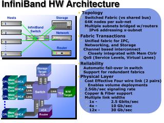
3.0 An IBA Overview • Comprehensive are the IB feature set: • defines a layered hardware protocol (the physical, link, network, transport and upper layer) • Packed Based Communication • Three link speeds: 1X = 2.5Gb/s (4 wire), 4X = 10Gb/s (16 wire), • 12X = 30Gb/s (48 wire). The date is encoded with 8b/10b • - PCB and Copper or Fibre Cable Interconnect • Support „in the box“ and „out of the box“ • Subnet Management Protocol with use a subnet management agent • RemoteDMA Support (memory manipulation semantic) • Channels message semantics (message queuing)
3.1 (1) IBA Network Node Node IBA Fabric Node Node Node At a high level, IBA is an interconnect for endnodes
3.1 (2) IBA Network Components IBA Subnet EndNode IBA Subnet EndNode Router EndNode EndNode IBA Subnet IBA Subnet Router EndNode EndNode EndNode An IBA network is subdivided into subnets with interconnected by routers. Endnodes may attached to a single subnets or attach to more than one subnets.
3.1 (3) IBA Subnet Components EndNode EndNode EndNode Switch Switch Subnet Manager Switch Switch Switch Router EndNode An IBA subnet is composed as shown of endnodes, switches routers and a subnet manager.Each IB device possible attach to a single switch or is connected with more than one switch (or/and directly with each other).
3.1 (4) Processor Node Processes Processes Processes „Channel message semantic“ Channel Adapter (Endnode) Channel Adapter (Endnode) Port Port Port Port
3.2 Consumer Queuing Model Consumer Work Queue WQE Work Queue Work Request WQE WQE WQE WQE Work Queue WQE WQE Hard- ware Completion Queue Work Completition CQE CQE CQE • Communication operation are described in WQR • Once submitte, aWQR -> WQE • WQE are executed by Cas • The end of a WQE is reported thru CQ • Once a WQE is finished, a CQE is placed on a CQ • Each consumer has ist own set of work, each QP is independent from the others
3.3 IBA Components This chapter explain the base of devices in the IBA-fabric • Links and Repeater • Channel Adapter • Switches • Router • Management Structure
3.3.2 Channel Adapter Memory QP QP QP QP SMA DMA Transport VL VL VL VL VL VL VL VL VL Port Port Port A CA has a DMA engine with special features, that allow remote and local DMA operations. Each port has ts own set of send and receive buffers. Buffering is channeled through VL (Virtual Lines), where each line has its own flow control. The implement Subnetmanager Agent (SMA) communicates with the subnet manager in the fabric.
3.3.3 Switches Packed Relay VL VL VL VL VL VL VL VL VL Port Port Port IBA switches are the fundamental routing component for intra-subnet routing. Switches interconnect links by relaying packets between the links. Switches have two ore more ports between which packets are relayed Switch elements are forwarding tables. Switches can be configured to forward either to a single location or to multiple devices.
3.3.4 Routers GRH Packed Relay VL VL VL VL VL VL VL VL VL Port Port Port IBA router are the routing component for inter-subnet routing. Each subnet is uniquely identified with a subnet ID. The router reads the Global Route Header from the IPv6 network layer Address for forwarding the packets. Each router forwards the packet through the next subnet to another router until the packet reach the target subnet. The last router sends the packet as the Destination LID to the subnet. The subnet manager configures routers with information about the subnet.
3.3.5 IBA-Management • IBA Management provides a subnet manager (SM) • SM is an entity directly attached to a subnet: Responsible for configuration and managing switches, routers, an CAs. • A SM can be implemented in other devices, such as a CA or a switch. • configures each CA port with a range of LIDs, GIDs and subnetIDs. • configures each switch with some LIDs, the subnetID, and with its forwarding database. • link failover • maintains the service databases for the subnet and provides a GUID to LID/GID resolution service. • error reporting • other services to ensure a solid connection
3.4.1 Physical Layer Structure Link Layer Byte Stream Power Management Link / Physical Link / Physical Encoded Lanes Hardware Management Power / Hot Swap Physical Link Electrical / Optical Signaling Mechanical Port Signals Connectors Physical Layer Backplane Cable Fiber Physical Port Physical Form Factor Chassis / Backplane
3.4.1 Physical Link 1 x Link 4 x Link 12 x Link
3.4.2 IBA Data Packet Format Start Delimiter Data End Delimiter Idles Packet LRH GRH BTH ETH Payload I Data ICRC VCRC Upper Layer Transport Layer Network Layer Link Layer Local Routing Header (has 8Bytes), Global Routing Header (40B), Base Transport Header (12B), Extended Transport Header (4,8,16or28B), Data (0-4kB), Immediate Data (4Bytes), Invariant CRC (4B), Variant CRC (2B)
3.4.3 Network Layer • The network layer describes the protocol for routing a packet between subnets. • Packets that are sent between subnets contain the GRH (Global Route Header. • The GRH identifiers the source and destination ports. • GRH is in the format of an IPv6 address. • The source places the GID of the destination in the GRH and the LID of the router in the LRH • The last router replaces the LRH with the LID of the destination.
3.4.4 Transport Types Service type Description Reliable Connection acknowledged, connection oriented Reliable Datagram acknowledged, multiplexed Unreliable Connection unacknowledged, connection oriented Unreliable Datagram unacknowledged, connectionless Raw Datagram unacknowledged, connectionless Note: Reliable Connection correspond to classic TCP, unreliable Connection UDP. With raw datagram it is possible IPv6 or Ethernet Packets/Frames to build and commnicate with other subnets.
4 IB Requirements • Storage systems are more and more connected to servers via networks => industry moves away from direkt attached storage to the network storage.This trend is resulted in modularity: • Both, server and storage platform architectures are more modular, to handle increased processing and capacity in less space • More need for dynamic I/O connectivity • A shift from server and storage platforms that share I/O resources • A move to rack servers (blades), that can be better managed as one computer
4 IB Market The IB market is segmented into two groups of vendors: IB Market Traditional IT Vendors „Pure play“ IB Companies - Network vendors - Management software vendors - System (both storage and servers) - Application and operation systems - Enterprise networking - Storage networking -Components of networking and microprcessor vendors
4 Road to IB Continued early Adopters Rapid Market Adoption First Volume 1x, 4x, 12x Early Pilots First Generation Beta Products Close to 50% of Servers with IB Support Growing Native IB for Server / Storage 1x Product Rapid Application / OS Support grows Application / OS Support grows futher 4x Prototype 2001 2002 2003 2004 2005 2006 Venture Funding Early Adopters Rapid Adoption 1x, 4x, 12x Early Product Development Commercial Deployments 1x, 4x Sizeable Native IB for Server / Storage First silicon Large Vendor of IB Product Rapid Application / OS Support grows Early Native IB Server / Storage Application / OS Support grows
4.1 First Vendors of IBA-Components JNI Mellanox Infiniswitch Voltaire VIEO System Vendors Banderacom IBA intel Sun IB Vendors IBM Dell Microsoft HP
4.2 Mellanox, a short representation • Mellanox is the leading supplier of IB-Components today. • The company was selected as one of the 50 most important companies in • the world. • Today Mellanox has 200 employees in multiple sites worldwide. • Headquarter in Santa Clara, CA. Designe, engineering and software • Development in Israel. • The company has invested more than 33million Dollar. • In January 2001, Mellanox delivered the Infinibridge MT21108, • a HCA and a 8 port switch • Infiniscale MT43132 (8 port switch) • Infiniscale MT43132M16S (16 Port Modular Switch) with 3 different configurations • 16 Ports copper or (12 copper and 4 optical) or (8 copper and 4 optical) • Infinihost MT23108, a TCA or HCA dualport (each 4x =10Gb/s) • NitroII, an IB Server Blade Chassis • NitroII, an IB Server Blade • NitroII, an IB 16 Port Switch Blade (4x)
4.2.1 InfiniHost MT23108 • Is a single chip dual-port 10Gb/s HCA with a PCI-X interface and integrated • physical layer (SerDes) interface. • MT23108 integrates eight 2.5Gb/s SerDes in a single 580pin package.This • Integration reduce power, systemcost, PCB size. • Full Hardware implementation of IBA • This reduce CPU overhead • InfiniHost devices are designed to be fully compatible with the IBTA1.0a • Sepcification =>interoperable with other divices • External DDR memory support for up to 16GB • This device is modular, so future needs of customers without losing • software compatibility. • A short introduction gives the orginal Mellanox presentation
4.2.2 InfiniBridge MT21108 • Integrated an eight port Channel Adapter and switch into a single chip • Four 1x links together to form a 4x (10Gb/s) link. • InfiniBridge devices support a high levels of integration. • Supporting up to eight data VL + a dedicated management lane per link. • Multicast Support for up to 1k Entries. • Maximum Transfer Unit (MTU) for up to 4kB. • Hardware CRC checking and generation.
5 Conclusion • Advantage • Seems to be a very good though. • Seems to be very good to manage. • Now first devices as hardware and software available (also Open Source [MPI, and so on...]) • Support all kind of Hardware and Software (Unix, Windows, Linux) • Perfekt scalability. • MPI-Software available. • Qualified to communication „in the box“ (better in future) and „out of the box“ (now) • In the future will be enable to bo a replacement of PCI • OEM Server vendors will be integrating silicon on to the board in Q4 2003 • Primary for Data-Center qualified. • Some drawbacks • Seems to be a very complex structure • Today in use as PCI-adapter • Suggestion • This discussion was an introduction to IBA. Next step will be interesset to inquire into deeper in Hardware in comparison to other as SCI or Myrinet. • Also very interesting, benchmark measuring for example MPI vs. Fast Ethernet.