Download
1 / 40
1.51k likes | 6.42k Vues
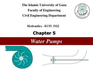
INTRODUCTION TO PUMPS, COMPRESSORS, FANS & BLOWERS. pumps increase the mechanical energy of the liquid, increasing its velocity, pressure, or elevation-or all three. Devices used to transport/move liquids through pipes & channels. PUMPS. Positive-Displacement Pumps. Centrifugal Pumps.

E N D
pumps increase the mechanical energy of the liquid, increasing its velocity, pressure, or elevation-or all three. Devices used to transport/move liquids through pipes & channels. PUMPS Positive-Displacement Pumps Centrifugal Pumps Rotary Pump Reciprocating Pump Vane Diaphragm Lobe Gear Piston Screw Plunger Spur-GP Internal-GP
Positive-Displacement Pumps • 2 subclasses: reciprocating pumps & rotary pumps. • Reciprocating pumps: the chamber is stationary cylinder that contains a piston or plunger. • Rotary pumps: the chambers moves from inlet to discharge and back to the inlet. chamber discharge inlet discharge chamber gear inlet Reciprocating pumps Rotary pump
Positive-Displacement Pumps:Reciprocating Pumps • Piston pump: • liquid is drawn through an inlet check valve into the cylinder by the withdrawal of a piston. • then the liquid is forced out through a discharge on the return stroke. discharge Check valve Piston chamber inlet Single-acting
Positive-Displacement Pumps:Reciprocating Pumps • most piston pumps are double-acting with liquid admitted alternately on each side of the piston so that one part of the cylinder is being filled while the other is being emptied. • the piston may be motor-driven through reducing gear or a steam cylinder may be used to drive the piston rod directly. • max. discharge pressure for commercial piston pumps is about 50 atm. discharge chamber Check valve inlet Piston Double-acting
Positive-Displacement Pumps:Reciprocating Pumps Double Acting Piston Pump:
Positive-Displacement Pumps:Reciprocating Pumps • Plunger pump: • are used for higher pressures. • instead of using pistons and piston rings, they make use of finely machined plungers of very small clearances in order to seal the liquid to be pumped. • the plungers are highly polished and made relatively long so that only very little liquid can escape through the clearances. • at the limit of its stroke, the plunger fills nearly all the space in the cylinder. • are single-acting and usually are motor driven. • they can discharge against a pressure of 1500 atm or more. discharge chamber inlet
Positive-Displacement Pumps:Reciprocating Pumps Plunger pump:
Positive-Displacement Pumps:Reciprocating Pumps • Diaphragm pump: • the reciprocating member is a flexible diaphragm of metal, plastic & rubber. • diaphragm pumps handle small to moderate amounts of liquid, up to about 100 gal/min, can develop pressures in excess of 100 atm.
Positive-Displacement Pumps:Reciprocating Pumps Diaphragm pump:
Positive-Displacement Pumps:Rotary Pumps • Unlike reciprocating pumps, rotary pumps contain no check valves. • Minimize leakage from the discharge space back to the suction space; they also limit the operating speed. • Rotary pumps operate best on clean, moderately viscous fluids such as light lubricating oil. • Discharge pressures up to 200 atm or more can be attained. chamber inlet discharge gear Rotary pump
Positive-Displacement Pumps:Rotary Pumps • Spur-gear pump • Intermeshing gears rotate with close clearance inside the casing. • Liquid entering the suction line at the bottom of the casing is caught in the spaces between the teeth & the casing & is carried around to the top of the casing & forced out the discharge. • liquid cannot short-circuit back to the suction because of the close meshing of the gears in the center of the pump. chamber inlet discharge gear Spur-gear pump
Positive-Displacement Pumps:Rotary Pumps • Internal-gear pump • A spur gear or pinion meshes with a ring gear with internal teeth. • Both gears are inside the casing. • The ring gear is coaxial with the inside of the casing, but the pinion, which is externally driven, is mounted eccentrically with respect to the center of the casing. • A stationary metal crescent fills the space between the two gears. • Liquid is carried from inlet to discharge by both gears, in the spaces between the gear teeth and the crescent. Internal-gear pump
Positive-Displacement Pumps:Rotary Pumps Lobe pump
Positive-Displacement Pumps:Rotary Pumps Lobe pump
Positive-Displacement Pumps:Rotary Pumps Vane pump
Positive-Displacement Pumps:Rotary Pumps Vane pump
Positive-Displacement Pumps:Rotary Pumps Vane pump
Positive-Displacement Pumps:Rotary Pumps Screw pump
Centrifugal pumps • The second major class of pumps, where mechanical energy of the liquid is increased by centrifugal action. • The liquid enters through a suction connection concentric with the axis of a high-speed rotary element called the impeller which carries radial vanes integrally cast in it. • Liquid flows outward in the spaces between the vanes and leaves the impeller in greater velocity with respect to the ground than at the entrance to the impeller. • In a properly functioning pump, the space between the vanes is completely filled with liquid flowing without cavitation. • The liquid leaving the outer periphery of the impeller is collected in a spiral casing called the volute and leaves the pump through a tangential discharge connection. • In the volute, the velocity head of the liquid from the impeller is converted to pressure head.
Centrifugal pumps • The power is applied to the fluid by the impeller and is transmitted to the impeller by the torque of the driveshaft, which usually is driven by direct-connected motor at constant speed, commonly at 1750 or 3450 r/min. • Centrifugal pumps constitute the most common type of pumping machinery in ordinary plant practice. • A common type uses a double-suction impeller, which accepts liquid from both sides.
Centrifugal pumps Single-suction centrifugal pump
Compressors & Blowers, Fans • are machines that move & compress gases. 1. Fansdischarge large volumes of gas (usually air) into spaces or large ducts -are low-speed machines that generate very low pressures, on the order of 0.04 atm. 2. Blowers:are high-speed rotary devices (using either positive displacement or centrifugal force) that develop a max. pressure of about 2 atm. 3. Compressors:are also positive-displacement or centrifugal machines, discharge at pressure from 2 atm to several thousand atmospheres.
Differences between fans, blowers & compressors Ratio of discharge pressure over suction pressure
Compressors • Positive-displacement compressors • Rotary positive-displacement compressors can be used for discharge pressures up to about 6 atm. • These devices include sliding-vane, screw-type, and liquid piston compressors. • For high to very high discharge pressures & modest flow rates, reciprocating compressor are the most common type. • These machines operate mechanically in the same way as reciprocating pumps, with the differences that leak prevention is more difficult and temperature rise is important. • The cylinder walls & cylinder heads are cored for cooling jackets using water refrigerant . • Reciprocating compressors are usually motor-driven & nearly always double acting.
Compressors Reciprocating compressor
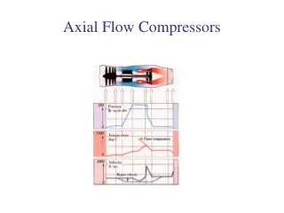
Compressors • Centrifugal compressors • are multistage units containing a series of impellers on a single shaft rotating at high speeds in massive casing. • internal channels lead from the discharge of one impeller to the inlet of the next. • these machines compress enormous volumes of air or process gas-up to 200,000 ft3/min (340,000 m3/h) at the inlet-to outlet pressure of 20 atm. • smaller-capacity machines discharge at pressures up to several hundred atmospheres. • interstage cooling is needed on the high-pressure units. • axial-flow machines handle even larger volumes of gas up to 600,000 ft3/min (1 x 10⁶ m3/h), but at lower discharge pressures of 2 to 12 atm. • in these units the rotor vanes propel the gas axially from one set of vanes directly to the next. Interstage cooling is normally not required.
Compressors Interior of centrifugal compressor
Blowers • Positive-displacement blower • These machines operates as gear pumps do except that, because of the special design of the “teeth", the clearance is only a few thousandths of an inch. • the relative position of the impellers is maintained precisely by heavy external gears. • A single-stage blower can discharge gas at 0.4 to 1 atm gauge, a two-stage blower at 2 atm. • Example: positive-displacement two-lobe blower.
Blowers Positive-displacement two-lobe blower
Blowers • Centrifugal blowers • In appearance it resembles a centrifugal pump, except that casing is narrower and diameters of casing & discharge scroll are relatively larger than in centrifugal pump. • The operating speed is high-3,600 r/min or more. • High speed and large impeller diameters are required because very high heads of low-density fluids are needed to generate modest pressure ratios. • Thus, the velocity approximately 10 times those in centrifugal pump. • Example: single-suction centrifugal blower
Blowers Single-suction centrifugal blower
Fans • Large fans usually centrifugal, operating exactly the same principle as the centrifugal pumps. • Their impeller blades may be curved forward, this would lead to instability in a pump, but not in a fan. • The impellers are mounted inside light sheet-metal casings. • Clearances are large & discharge heads low, from 5 to 60 in. (130 to 1500 mm) H2O. • Sometimes, as in ventilating fans, nearly all the added energy is converted to velocity energy and almost none to pressure head.
Fans Impellers for centrifugal fans