Simulated Active Control in a VARTM Process Using Induction Heating
Simulated Active Control in a VARTM Process Using Induction Heating. Richard Johnson and Ranga Pitchumani University of Connecticut Composites Processing Laboratory 191 Auditorium Road, Storrs, CT 06269 www.engr.uconn.edu/cml

Simulated Active Control in a VARTM Process Using Induction Heating
E N D
Presentation Transcript
Simulated Active Control in a VARTM Process Using Induction Heating Richard Johnson and Ranga Pitchumani University of Connecticut Composites Processing Laboratory 191 Auditorium Road, Storrs, CT 06269 www.engr.uconn.edu/cml Presented at the 14th International Conference on Composite Materials, July 18, 2003, San Diego, CA Sponsors: Office of Naval Research, National Science Foundation
Outline • Introduction • Experimental setup • Numerical modeling • Active control • Temperature • Motion • Numerical Study • Ongoing work
Process Description • Vacuum Assisted Resin Transfer Molding (VARTM) • Preform permeation is a critical step • voids and dry spots = poor part quality
Control • Boundary control methods show reduced controllability further from the controlled boundary • Need for more localized control D. Nielsen, R. Pitchumani (COMPOS PART A-APPL S: 2001) (COMPOS SCI TECHNOL: 2002) (POLYM COMPOSITE: 2002)
Mold Fill - Heterogeneous Preform Layup • Heterogeneous layups can lead to dry spots • Proposed control scheme: Active localized heating Line Source Low Permeability Patch Line Vacuum
Mold Fill with Heating • Addition of heat to the low permeability area • improved uniformity • elimination of voids and dry spots Line Source Low Permeability Patch Uniformly Heated to 60C Line Vacuum
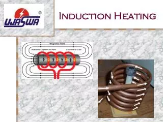
Heating Methods • Resistive • contact required • Ultrasonic • contact required • possibility of ultrasonic horn melting vacuum bags • Laser • requires fast scanning of intentionally defocused beam • Induction • compact, mobile heating unit • requires susceptors
emfi Induction coil geometry Numerical Modeling - Induction Heating • Induction power calculation • current conservation at the nodes of the susceptor mesh • summation of voltages in a loop = emf I2 I1 I3 I4
Numerical Modeling - Flow • Flow governed by Darcy’s law: • Pressure distribution: • five-point Laplacian scheme • Darcy’s law used to find velocities • volume tracking method used to find the flow front locations • BC’s • Walls impenetrable with no slip • vacuum line defined with negative pressure • inlet defined by atmospheric pressure at the surface of the source container • Permeability • Carman-Kozeny relationship:
Numerical Modeling - Heat Transfer • Energy equation: • 3-D control volume analysis and ADI method (Douglas and Gunn: 1964) • BC’s • mold sides considered adiabatic • top surface of the vacuum bag and bottom surface of the mold considered convective • inlet and outlet at ambient temperature
Numerical Modeling • Coupled by viscosity • Arrhenius equation: • flow is dependent on temperature through viscosity • temperature is dependent on the flow • Iterative solution • convergence based on temperature: • Time step varied • mesh Fourier number • mesh Courant numbers
Temperature Heat the resin to supply aid to flow permeation Fundamental challenge: Limit temperatures so as to not gel the resin during filling Motion The induction coil must be moved so as to heat the appropriate regions Only x and y direction motion are considered Active Control
Maximize the coil voltage - achieving the fastest fill times Specified upper bound: 100°C Temperature measurement is difficult Lumped capacitance approach Temperature Control
y - direction motion Maintain the coil above filled regions Keep the coil just behind the flow front Allows for control where the preform layup is not know a priori x - direction motion Keep the coil behind the location of maximum lag Use delays to avoid potential problems Motion control
Coil path corresponds to the low permeability areas Improved uniformity over unheated case Preform Layup: Predetermined Random
Coil location remains at the right side of the mold Notable improvement in uniformity Preform Layup : Side Strip
Demonstrates a practical application Coil remains centered in the mold Can potentially avoid void entrapment Preform Layup: Center Patch
Shows improved uniformity Coil location follows the lag location Preform Layup: Computer Selected Random
Minimum RMS error: 2–10 second delay Physical limitation: coil power up from standby to 200V: 7 sec Recommended delay: 7-10 Seconds Delay Times
Summary & Ongoing Work • Summary • Numerical model of the VARTM process • Induction heating control • Ongoing Work • Implement control logic on physical setup • Incorporate resin cure kinetics in the numerical model • Replace upper control bound with a function of the cure kinetics