Download
1 / 10
150 likes | 1.1k Vues
MODELING OF INDUCTION HARDENING PROCESS PART 1: INDUCTION HEATING. Dr. Jiankun Yuan Prof. Yiming (Kevin) Rong. Acknowledgement: This project is partially supported by Delphi and CHTE at WPI. Dr. Q. Lu was involved in the early work of the project. http://me.wpi.edu/~camlab.

E N D
MODELING OF INDUCTION HARDENING PROCESSPART 1: INDUCTION HEATING Dr. Jiankun Yuan Prof. Yiming (Kevin) Rong Acknowledgement: This project is partially supported by Delphi and CHTE at WPI. Dr. Q. Lu was involved in the early work of the project. http://me.wpi.edu/~camlab
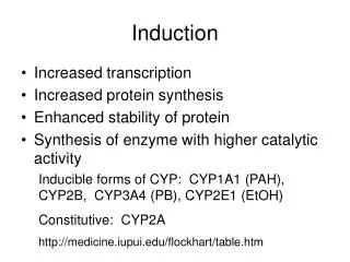
Induction: Why Induction Heat Treatment? Advantages Greatly shortened heat treatment cycle Highly selective Highly energy efficiency Less-pollution process Practical Problems • Lack of systematic heating time and temperature distribution control inside WP. • Nonlinear effect of material properties. • Lack phase transformation data inside WP for hardness and residual stress determination. • Evaluate combination effect of AC power density, frequency and gap on final hardness pattern. • Trial and error, cost and design period. Research content:FEM based electromagnetic/thermal analysis + quenching analysis + hardening analysis Numerical modeling may provide better prediction Research objective: (1)ProvideT field, time history inside WP (2) Determine formed content of martensite, pearlite and bainite. (3) Determine hardness distribution in WP. (4) Guidance for induction system design.
Introduction: Induction Hardening Process • Induction heating: metal parts heated to austenite Phase • Fast quenching process transforms austenite to martensite phase workpiece Inductor/coil Heating process • Martensite content determines the hardness Joule heat by eddy current • Martensitic structure is the most hardest microstructure Electromagnetic field High freq. AC power Induction coil
(b) FEA model (a) WP geometry QN QN QW QEt QR+ QCV QE QC QB WP Coil (Outside) QS QS (c) Interior element (d) Surface element Principle: Electromagnetic and Thermal Analysis Electromagnetic Analysis Thermal Analysis with finite element model Input AC power to coil Calculation of magnetic vector potential (A) Calculation of magnetic flux density (B) B = A (Gauss’ Law for magnetic field) Calculation of magnetic field intensity (H) H = B / Calculation of electric field intensity (E) (Faraday’s Law) Calculation of electric field density (D) D = E Calculation of current density (J) (Ampere’s Circuital Law) Heat conduction Calculation of Inducting heat (Qinduction) Qinduction = E J = J2/ Output: Heat generation Qinduction in WP Induced Joule heat Heat convection Heat radiation
Case Study: Complex Surface Hardening concave Material: Carbon Steel, AISI 1070 convex Automotive parts from Delphi Inc., Sandusky,Ohio • Concave and convex on surface of workpiece make the heating process not easy to control. Real spindle to be hardened Geometry Model • ANSYS system is employed for the analysis. • Mesh should be much finer at locations of convex and concave in both coil and workpiece. Mesh generated by ANSYS FEA model and B.C.
Case Study: Material Properties -- AISI 1070 (a) Electromagnetic Properties conductivity WP relative permeability Electrical Resistivity (b) Thermal Properties Emissivity Specific heat Convection coefficient
Effect of current density distribution • Constant current distribution in coil can not result in good heating pattern, especially at concaves of workpiece • Better hardened pattern resulted from modification of Finer coil mesh and enhanced coil current density at area neighboring to surface concaves of workpiece. • Enhanced coil current density suggests utilization of magnetic controller at those area in coil design process. Physically this can be fulfilled by magnetic controller. (a1) Constant current distribution in coil (a2) heated pattern (b1) Adjusted current distribution in coil (b2) heated pattern
Case Study:Temperature Variation with Time in Induction Heating Process t=0.5s t=2s Total heating time th = 7.05s f=9600Hz s=1.27mm J=1.256e6 A/m2 t=4s
Case Study: Heating Curves Summary • A finite element method based modeling system is developed to analyze the coupled electromagnetic/thermal process in induction heating andimplemented in ANSYS package, with following capabilities. • Provide electrical and magnetic field strength distribution. • Provide instantaneous temperature field data in workpiece. • Provide Temperature history at any location in heating process. • Provide guidance for inductor/coil design based on adjustment of current density distribution and desired heating patterns.