Download
1 / 23
240 likes | 485 Vues
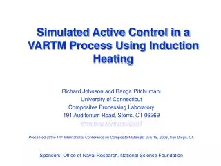
Induction Heating Assisted Permeation Enhancement for the VARTM Process. Richard Johnson and Ranga Pitchumani University of Connecticut Composites Processing Laboratory 191 Auditorium Road, Storrs, CT 06269 www.engr.uconn.edu/cml Sponsors: NSF(CTS-9912093), AFOSR(f-49620-01-1-0521)

E N D
Induction Heating Assisted Permeation Enhancement for the VARTM Process Richard Johnson and Ranga Pitchumani University of Connecticut Composites Processing Laboratory 191 Auditorium Road, Storrs, CT 06269 www.engr.uconn.edu/cml Sponsors: NSF(CTS-9912093), AFOSR(f-49620-01-1-0521) Presented at the International SAMPE Technical Conference. Nov. 5th 2002. Baltimore, MD
Outline • Introduction to VARTM • Process description • Controlling the mold filling stage • Numerical Modeling • Nonisothermal mold filling with induction heating • Experimental Setup • Model Validation • Results • Questions
Process Description • Vacuum Assisted Resin Transfer Molding (VARTM) • Preform permeation is a critical step • voids and dry spots = poor part quality
Process Difficulties - Filling • Variation in preform permeability from that predicted by theory leads to non-uniform fill • uncertainty in pore structure • heterogeneous preform layups • race tracking • Need for flow control
Control • Boundary control methods show reduced controllability further from the controlled boundary • Need for more localized control D. Nielsen, R. Pitchumani (COMPOS PART A-APPL S: 2001) (COMPOS SCI TECHNOL: 2002) (POLYM COMPOSITE: 2002)
Mold Fill - Heterogeneous Preform Layup • Heterogeneous layups can lead to dry spots • Proposed control scheme: Active localized heating Line Source Low Permeability Patch Line Vacuum
Mold Fill with Heating • Addition of heat to the low permeability area • improved uniformity • elimination of voids and dry spots Line Source Low Permeability Patch Uniformly Heated to 60C Line Vacuum
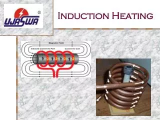
Heating Methods • Resistive • contact required • Ultrasonic • contact required • possibility of ultrasonic horn melting vacuum bags • Induction • compact, mobile heating unit • requires susceptors • Laser • requires fast scanning of intentionally defocused beam
emfi Induction coil geometry Numerical Modeling - Induction Heating • Induction power calculation • current conservation at the nodes of the susceptor mesh • summation of voltages in a loop = emf I2 I1 I3 I4
Numerical Modeling - Flow • Flow governed by Darcy’s law: • Pressure distribution: • five-point Laplacian scheme • Darcy’s law used to find velocities • volume tracking method used to find the flow front locations • BC’s • Walls impenetrable with no slip • vacuum line defined with negative pressure • inlet defined by atmospheric pressure at the surface of the source container • Permeability • Carman-Kozeny relationship: • Cz values from literature:
Numerical Modeling - Heat Transfer • Energy equation: • 3-D control volume analysis and ADI method (Douglas and Gunn: 1964) • BC’s • mold sides considered adiabatic • top surface of the vacuum bag and bottom surface of the mold considered convective • inlet and outlet at ambient temperature
Numerical Modeling • Coupled by viscosity • Arrhenius equation: • flow is dependent on temperature through viscosity • temperature is dependent on the flow • Iterative solution • convergence based on temperature: • Time step varied • mesh Courant number • mesh Fourier numbers
Model Validation Vacuum Level: 77kPa Coil Voltage: 125V Coil Position: 5.08cm P = -77 kPa No Heating Vacuum Level: 77kPa Coil Voltage: 140V Coil Position: 15.24cm
Numerical Study • Parametric study • varied parameters • induction coil location • (stationary in each simulation) • induction coil voltage • vacuum level • permeability ratio
Definition of maximum and quasi-steady-state temperature If the maximum allowed temperature is 100oC then Vmax = 85V Results - Upper Bound
Coil location: 15.24 cm Vacuum level: -77 kPa Coil location: 5.08 cm Vacuum level: -77kPa Results - Lower Bound
Results - Central Patch • vacuum level higher allowable voltages • Coil locations closer to the inlet • upper bound higher allowable voltages • lower bound increases sharply with permeability ratio 10.16 cm 5.08 cm 15.24 cm
Results - Central Patch with Race Tracking • Comparison to non-race tracking cases • similar upper bound • more restrictive lower bound • lower permeability ratios requiring heating • higher required voltages at the same permeability ratio 10.16 cm 5.08 cm 15.24 cm
Numerical Study • Parametric study varied parameters • permeability ratio • induction voltage • coil position Merit function
Ideal coil location and RMS error Ideal coil location and quasi-steady state temperature Results - Side by Side
Summary • Description of the VARTM process • Numerical model for non-isothermal flow in VARTM with induction heating • Experimental setup • Parametric studies • two preform layups • varied parameters: • induction coil location • vacuum level • induction coil voltage • permeability ratio • processing windows • Current work: active control