Stirred-Tank Heating Process
Stirred-Tank Heating Process. Chapter 2. Figure 2.3 Stirred-tank heating process with constant holdup, V . Stirred-Tank Heating Process (cont’d.). Assumptions: Perfect mixing; thus, the exit temperature T is also the temperature of the tank contents.

Stirred-Tank Heating Process
E N D
Presentation Transcript
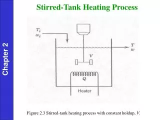
Stirred-Tank Heating Process Chapter 2 Figure 2.3 Stirred-tank heating process with constant holdup, V.
Stirred-Tank Heating Process (cont’d.) • Assumptions: • Perfect mixing; thus, the exit temperature T is also the temperature of the tank contents. • The liquid holdup V is constant because the inlet and outlet flow rates are equal. • The density and heat capacity C of the liquid are assumed to be constant. Thus, their temperature dependence is neglected. • Heat losses are negligible. Chapter 2
For the processes and examples considered in this book, it • is appropriate to make two assumptions: • Changes in potential energy and kinetic energy can be neglected because they are small in comparison with changes in internal energy. • The net rate of work can be neglected because it is small compared to the rates of heat transfer and convection. • For these reasonable assumptions, the energy balance in • Eq. 2-8 can be written as Chapter 2
Model Development - I For a pure liquid at low or moderate pressures, the internal energy is approximately equal to the enthalpy, Uint , and H depends only on temperature. Consequently, in the subsequent development, we assume that Uint = H and where the caret (^) means per unit mass. As shown in Appendix B, a differential change in temperature, dT, produces a corresponding change in the internal energy per unit mass, Chapter 2 where C is the constant pressure heat capacity (assumed to be constant). The total internal energy of the liquid in the tank is:
Model Development - II An expression for the rate of internal energy accumulation can be derived from Eqs. (2-29) and (2-30): Note that this term appears in the general energy balance of Eq. 2-10. Chapter 2 Suppose that the liquid in the tank is at a temperature T and has an enthalpy, . Integrating Eq. 2-29 from a reference temperature Tref to T gives, where is the value of at Tref. Without loss of generality, we assume that (see Appendix B). Thus, (2-32) can be written as:
Model Development - III For the inlet stream Substituting (2-33) and (2-34) into the convection term of (2-10) gives: Chapter 2 Finally, substitution of (2-31) and (2-35) into (2-10)
Table 2.2. Degrees of Freedom Analysis • List all quantities in the model that are known constants (or parameters that can be specified) on the basis of equipment dimensions, known physical properties, etc. • Determine the number of equations NE and the number of process variables, NV. Note that time t is not considered to be a process variable because it is neither a process input nor a process output. • Calculate the number of degrees of freedom, NF = NV - NE. • Identify the NE output variables that will be obtained by solving the process model. • Identify the NF input variables that must be specified as either disturbance variables or manipulated variables, in order to utilize the NF degrees of freedom. Chapter 2
Degrees of Freedom Analysis for the Stirred-Tank Model: 3 parameters: 4 variables: 1 equation: Eq. 2-36 Thus the degrees of freedom are NF = 4 – 1 = 3. The process variables are classified as: Chapter 2 1 output variable: T 3 input variables: Ti, w, Q For temperature control purposes, it is reasonable to classify the three inputs as: 2 disturbance variables: Ti, w 1 manipulated variable: Q
Degrees of Freedom Analysis for the Stirred-Tank Model: 3 parameters: 4 variables: 1 equation: Eq. 2-36 Thus the degrees of freedom are NF = 4 – 1 = 3. The process variables are classified as: 1 output variable: T 3 input variables: Ti, w, Q For temperature control purposes, it is reasonable to classify the three inputs as: 2 disturbance variables: Ti, w 1 manipulated variable: Q