Download
1 / 17
170 likes | 424 Vues
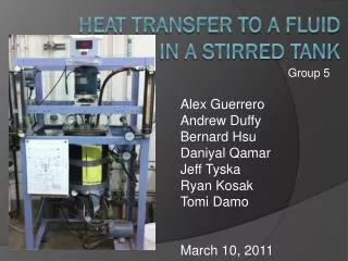
Group 5 Alex Guerrero Andrew Duffy Bernard Hsu Daniyal Qamar Jeff Tyska Ryan Kosak Tomi Damo March 10, 2011. Heat Transfer to A fluid in a stirred tank. Introduction. The stirred tank is an important experiment concerning the heat transfer (HT) to a fluid

E N D
Group 5 • Alex Guerrero • Andrew Duffy • Bernard Hsu • DaniyalQamar • Jeff Tyska • Ryan Kosak • TomiDamo • March 10, 2011 Heat Transfer to A fluid in a stirred tank
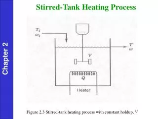
Introduction • The stirred tank is an important experiment concerning the heat transfer (HT) to a fluid • Due to the great variety of types of stirred tanks there are only a few reliable correlations. • A steam jacket allows HT to the internal liquid and aninternal cooling coil uses cold water to remove heat. • Liquid exits into a HXthat is also fed with cold water. Cooled liquid is returned to the tank.
Purpose • The purpose of this laboratory experiment is to measure the heat transfer coefficient (HTC) between the fluid and the inside tank wall. • These measurements will be taken during three HT processes involving the stirred tank unit.
Purpose • These three processes include: • Steady State Unbaffled Tank • Steady State Baffled Tank • Baffles deter vortexes, improving fluid mixing increases heat transfer rate. • Unsteady State UnbaffledTank • Can then determine the dependence of the HTC on the impeller speed, fluid properties, and the use of baffles.
Theory • The HT terms consist of: • HTacross the internal fluid to the wall of the stirred tank • HT across the tank wall • HT from the condensing steam to the tank wall
Theory • For Steady State: Q13 = U(t1-t3)A • Use this equation to solve for overall HTC. • t1 is the temp in the tank,t2 is the temp of the steam trap outlet, and A is the tank area
Theory Q13 = U(t1-t3)A • Q13, HT from steam to fluid in vessel, is the difference between heat removed in cooling coils and the heat removed by the HX: Q13 = Qc – Qhx *Qc and Qhx can each be solved using Q=mCpΔt
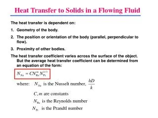
Theory • ho, the HTC at outer wall surface, can be solved using: ho = 2960 (DT,o/mst)1/3 • where DT,o is the tank diameter and mst is the mass flow rate of steam • mst can be found be calculating the volume of steam condensate collected per time interval
Theory • To solve for hi, HTC at inner wall, use the relation: hi = (1/U + 1/ho)-1 • For unsteady state use the relation: AU(t1-t3) = mCp[dt3/dΘ] • In this case, [dt3/dΘ] is the slope of the graph of unsteady state heating vs. time
1 3 2 10 6 8 11 4 9 7 5 Apparatus
Apparatus 12 18 17 14 15 13 16
Procedure • Steady State Stirred Tank (Unbaffled): • Fill tank with water to about 2 inches from top. Measure height of liquid level. • Turn on impeller motor and set to ~ 100 RPM. • Turn on cooling water to cooling coils. • Turn on cooling water to HX. • Close pump discharge and pump suction valves. Open pump bypass valve.
Procedure • Steady State Stirred Tank (Unbaffled): • Turn on pump. • Open cooling water valve to steam condenser. • Open steam inlet valve. • After reaching steady state record flow rates, temperatures, and impeller speed. • Repeat for different impeller speeds. • *Note: Adjust HX flow rate to a higher temperature to obtain data for two different temperatures at constant impeller speeds.
Procedure Continued • Steady State Stirred Tank (Baffled): • Repeat steps 1-10 of previous procedureusing the mechanical baffles. • Unsteady State: • Open water inlet valve, fill tank. • Close all the valves for the cooling coil and recirculation water lines. • Turn on cooling water to condenser. • Open the condenser water valve, slightly open steam valve. • Turn on the impeller. • Adjust impeller speed to speeds used in SS trials. • Open the steam valve. • Measure the temp and time intervals and record data (until reach 85 oC).
Safety • Take note of equipment exposed to high heat steam and use heat gloves when necessary. • Avoid the impeller when in use. • Be cautious of water spills to prevent slipping.
References • Bird, R. B., Warren E. Stewart, and Edwin N. Lightfoot. Transport Phenomena. 2nd ed. New York, NY: Jonh Wiley & Sons, Inc., 2002 • Perry, Robert H., and Don W. Green. Perry's Chemical Engineers' Handbook. New York: McGraw-Hill Professional, 2007. • University of Illinois at Chicago - UIC. Web. 13 Sept. 2010. <http://www.uic.edu/depts/chme/UnitOps/entry.html>. • McCabe, Warren L., Julian C. Smith, and Peter Harriott. Unit Operations of Chemical Engineering. New York: McGraw-Hill, 1993. (pp: 1058-1065) Print. • Wankat, Phillip C. Separation Process Engineering. (2nd Edition). Boston, MA: Pearson Education, Inc., 2007. (pp: 573 – 579) Print.