Power Semiconductor Systems I
Power Semiconductor Systems I. Author: Ales Havel E-mail: ales.havel@vsb.cz Phone number: 4287 Headquarters: E227 Web page: http://homen.vsb.cz/~ hav278 /. Presentation contents. Power semiconductor devices Power diode Thyristors GTO thyristor IGCT thyristor MCT Power transistors


Power Semiconductor Systems I
E N D
Presentation Transcript
Power Semiconductor Systems I Author: Ales Havel E-mail:ales.havel@vsb.cz Phone number: 4287 Headquarters: E227 Web page: http://homen.vsb.cz/~hav278/
Presentation contents • Power semiconductor devices • Power diode • Thyristors • GTO thyristor • IGCT thyristor • MCT • Power transistors • Bipolar transistor (BJT) • MOSFET • IGBT • Main types of converters
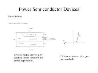
Power diode Single P-N junction creates a diode that has two terminals: an anode (A) and a cathode (K). Diode structure and symbol
Power diode • Steady State V-I Characteristic of a Diode
Power diode • Dynamic parameters • Dynamic parameters relate to fast transition from ON to OFF states • Not only speed of transition between the two states is important, but also changes in the diode voltage and current during the transition should be taken into account.
Power diode • Transient V-I Characteristic of a Diode
Power diode • Main requirements: • reverse voltage Uras high as possible • voltage drop UFas low as possible • turn-off speedas high as possible • Qrr(reverse recovery charge)as low as possible
Thyristor • Thyristor (SCR – Semiconductor Controlled Rectifier) is a controlled semiconductor device of 4-layer PNPN structure with 3 PN junctions. Thyristor schematic symbol and structure
Thyristor • Steady-State V-I Characteristic of a Thyristor
Thyristor • Transient V-I Characteristics of a Thyristor
Thyristor • Switching conditions: • To turn-on: • UA = UD > 0 (forward blocking state) • Bring sufficiently high current IG into the gate • To turn-off: • The forward current has to stop flowing • A control electrode cannot effect thyristor turn-off • The IL current (latching current – min. value to turn on) • The IH current (holding current – min. value to stay open)
GTO thyristor GTO thyristor (Gate Turn-Off thyristor) is a semiconductor device built on the same principle as traditional thyristor. The difference is in the case that the GTO could be turned of by the negative gate current. GTO Thyristor schematic symbol and structure
MCT thyristor • MOS Controlled Thyristor (MCT) is voltage controlled fully controllable thyristor. • The MCT is similar in operation with GTO thyristor, but it has voltage controlled insulated gate. • It has two MOSFETs in its equivalent circuit. One is responsible for turn-on and the another is responsible for turn-off.
BJT transistor • A Bipolar (Junction) Transistor (BJT) is a three-terminal electronic device constructed of doped semiconductor material and may be used in amplifying or switching applications. Bipolar transistors are so named because their operation involves both electrons and holes. • The BJT has three terminals, corresponding to the three layers of semiconductor – an emitter, a base, and a collector. Schematic mark
BJT transistor • Main principle of the BJT transistor Collector Base Emitter Switching the BJT transistor
BJT transistor • Static characteristics Transfer Output Input Reverse
MOSFET transistor • A Power MOSFET is a specific type of metal oxide semiconductor field-effect transistor that has been designed to handle large amounts of power. N-Channel P-Channel Depletion mode Enhancement mode
MOSFET transistor • Switching MOSFET
MOSFET transistor • Static characteristic MOSFET Linear area Saturation area
IGBT transistor • The Insulated Gate Bipolar Transistor (IGBT) is a minority-carrier device with high input impedance and large bipolar current-carrying capability. Symbol and equivalent circuit model of an IGBT
IGBT tranzistor • Switching IGBT
IGBT tranzistor • Absolute maximum ratings
IGBT tranzistor • Electrical characteristic
IGBT • Thermal characteristic
IGBT • The IGBT is suitable for many applications in power electronics, especially in Pulse Width Modulated (PWM) servo and three-phase drives requiring high dynamic range control and low noise. • It also can be used in Uninterruptible Power Supplies (UPS), Switched-Mode Power Supplies (SMPS), and other power circuits requiring high switching repetition rates. • IGBT improves dynamic performance and efficiency and reduced the level of audible noise. It is equally suitable in resonant-mode converter circuits. • Optimized IGBT is available for both low conduction losses and low switching losses.
Power converters • A power semiconductor converter is an electrical device for converting electrical energy.