Comprehensive Overview of Power Semiconductor Convertors and Their Applications
This presentation by Ales Havel delves into power semiconductor converters, focusing on AC-DC, DC-DC, DC-AC, and AC-AC converters. It covers the main types, including single-phase and three-phase rectifiers, construction possibilities, and wiring. The session includes mathematical relations and load voltage and current waveforms, providing neat examples for better understanding. Key aspects such as properties of rectifiers, control options, and important calculations for output voltage are discussed, making it essential for those interested in the field of power electronics.

Comprehensive Overview of Power Semiconductor Convertors and Their Applications
E N D
Presentation Transcript
Power Semiconductor Systems I Author: Ales Havel E-mail:ales.havel@vsb.cz Phone number: 4287 Headquarters: E227 Web page: http://homen.vsb.cz/~hav278/
Presentation contents • Main types of converters • AC-DC converters • Single phase rectifiers • Construction possibilities, wiring • Load voltage and current waveforms • Mathematics • Neat examples • Three phase rectifiers • Construction possibilities, wiring • Load voltage and current waveforms • Mathematics • Neat examples • DC-DC converters • DC-AC converters • AC-AC converters
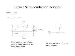
Power converters • A power semiconductor converter is an electrical device for converting electrical energy.
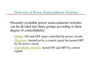
Division of AC/DC converters • Properties of rectifiers • Number of input phases • Single phase rectifiers • Three phase rectifiers • n – phase rectifiers • Number of pulses • P = 1, 2, 3, 6… • Possibilities of output voltage control • Without control • Diode rectifiers • Half-controlled rectifiers • Diodes + Thyristors • Full-controlled rectifiers • Thyristors • Wiring • Bridge rectifiers • Node rectifiers
Half-wave single phase diode rectifiers Voltage Resistive load Current Voltage Inductive load Current
Half-wave single phase diode rectifiers Voltage R+L load Current Voltage R+L+D0 load Current
Half-wave single phase diode rectifiers Voltage R+C load Current Voltage R+V load Current
Two pulse diode rectifiers Voltage Current
Important mathematical relations The output AVG voltage of diode rectifier or thyristor rectifier with control angle α = 0°: The output AVG voltage of thyristor rectifier with control angle α. Condition 1: The load current must be continuous Condition 2: No parallel bypass diode on the load
Example 1- submission Calculate the output AVG voltage of the 2-pulse bridge controlled rectifier, if you know the following values: α = 60°, U1 = 230V
Example 1- solution a) General calculation approach: b) Calculation utilizing the basic relation: c) Calculation utilizing the table values:
Example 1- question? How will change the output AVG voltage value if we use the bypass diode parallel to the load? Solution: