Digital Communication
Digital Communication. Analog Source. A/D. Binary Bytes. Symbol Decision. Symbol State Modulation. Binary Bytes. Symbol Modulated Carrier. RX. D/A. Recovered Analog. Coding.

Digital Communication
E N D
Presentation Transcript
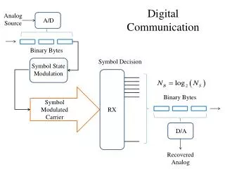
Digital Communication Analog Source A/D Binary Bytes Symbol Decision Symbol State Modulation Binary Bytes Symbol Modulated Carrier RX D/A Recovered Analog
Coding The previous diagram does not show the data encoding and decoding process. We will discuss that in great depth at a later time. That is where the real advantage of digital communication accrues, because that is where data security (encryption and error correction) is accomplished. For now, we will be satisfied with a simple system, and survey some of the A/D and D/A techniques in common use.
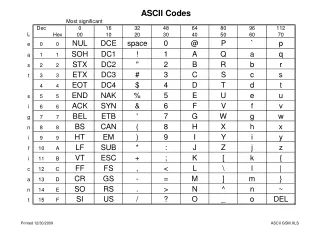
A/D Basics • Sampling Resolution: • An analog value (sample) is to be represented by an integer, n, within a range 0 to (N-1), corresponding to an analog range of xminto xmax. • Any integer therefore represents an analog value lying in a range of + (xmax - xmin)/2N. • This is called quantization error, and represents an inherent additional noise. • The number of bits in a sample word is B = log2(N), and must be chosen such that the quantization noise does not appreciably degrade the specified system signal to noise ratio. • Sampling Theorem: • Assume an analog sinusoid having frequency fx is sampled at intervals Ts = 1/Fs. • The sample sequence will be identical for analog sinusoids having frequency fx+ pFs , where p is any integer. • Therefore, the double sided bandwidth of the input signal must be less than Fs , or +Fs/2.
Time Division Multiplexing Multiple data sources can share a communications channel by transmitting data frames at the sample frequency, and each data frame is subdivided into dedicated time slots corresponding to each individual sampled data source. Within each time slot, the state of the carrier may be determined to represent the value of the sampled data, by several methods. • PAM • The amplitude of the carrier is set to the amplitude of the data sample for the entire duration of the time slot • PWM • The amplitude is fixed, but the pulse duration (as a % of the time slot) is set to represent the amplitude of the sample. • PPM • A pulse with fixed amplitude and fixed duration is delayed within the time slot by an amount corresponding to the amplitude of the sample. • PCM • A digital code representing the sample value is transmitted during each time slot.
Inter-symbol Interference The state of a channel cannot instantaneously change from one state to another – therefore there is always some remnant of the previous symbol contaminating the present symbol. This can be mitigated somewhat by utilizing an equalization filter, characterized by rolloff factor “r” The maximum symbol rate that can be accommodated by a channel having bandwidth BT is: Fs(max) = 2BT/(1+r)