RV Furnaces
1.05k likes | 1.32k Vues
RV Furnaces. Factory Information. 676 Broadway Dayton, Tennessee 37321 Website: www.rvcomfort.com E-mail address: smcsales@suburbanmfg.com. Factory Support Phone Numbers. Phone: 423 775-2131 Fax: 423 775-7015 Business Hours: 8 AM to 5 PM Eastern Time.

RV Furnaces
E N D
Presentation Transcript
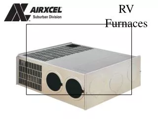
RV Furnaces
Factory Information • 676 Broadway Dayton, Tennessee 37321 Website: www.rvcomfort.com E-mail address: smcsales@suburbanmfg.com
Factory Support Phone Numbers Phone: 423 775-2131 Fax: 423 775-7015 Business Hours: 8 AM to 5 PM Eastern Time
Factory Technical Service Extension 7102 • Service Manager • Ronnie Ellison ext. 7007 • Assistant Service Manager • Louie Richard ext. 7005
Factory Customer Service Extension 7101 • Customer Service Manager • Sheila Cheek ext. 7016 • Customer Service • Vicki May ext. 6372 • Linda Welch ext. 6373 • Jennifer Yawn ext. 6371
NT Lightweight Series Furnace • NT16/20 SQ • Side duct discharge.
NT Series Furnace • NT16/20 SEQ • Direct discharge
NT Heavyweight Series Furnace • NT30/34SP NT40 • Side and bottom duct discharge.
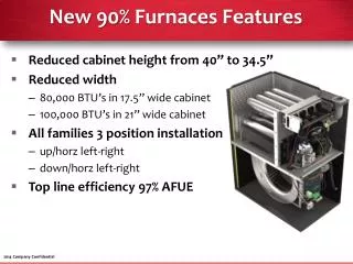
Park Model Furnaces(120 VAC) • P40 • Side and bottom duct discharge. • Can be field converted to natural gas. • Same dimensions as NT series furnace
Rear & Front Gas • SF 20/25/30/35/42Q • Rear gas connection • Service through outside door application. • Front, bottom, top & side duct discharge. • SF20/25/30/35/42FQ • Front gas connection • Service from inside coach. • Front, bottom, top & side duct discharge.
Vertical Mount Furnaces • SFV 20/25/30/35/42Q • Rear gas connection • Service through outside door application. • Front, bottom, top & side duct discharge. • SFV 20/25/30/35/42FQ • Front gas connection • Service from inside coach. • Front, bottom, top & side duct discharge.
SH Series Furnace • SH35/42 SH35/42 F • Front & Rear gas connection. • Front, bottom, top & side duct discharge. • 9 ¼ inches H x 17 W inches x 20 inches D
SHD-2542 Furnace • Dual Rate 25,000 & 42,000 BTU • Front, bottom, top & side duct discharge
Equipment • Volt-Ohm Meter • Manometer (calibrate monthly with U-tube) • Leak Check Solution • Assorted Hand Tools
Gas Pressure • 11 inches W.C. Minimum • 14 inches W.C. Maximum • W.C. water column • Test with at least half of the appliances operating.
Voltage • 10.5 Volts DC minimum • 13.5 Volts DC maximum
Pressure Drop Test • Install pressure gauge into gas system • Use leak check solution on fitting • Eight (8) inches W.C. for three (3) minutes
Wire Connections • Four wires are used for connections. • Red 12 VDC positive. • Yellow 12 VDC negative. • Blue thermostat positive +. • Blue thermostat return voltage.
Thermostat • Bi-metal thermostat shown. • Device used to control operation of furnace by reacting to ambient temperature.
On/Off Switch • Device used to control power to the module board.
Rewire kits available to update non fan control MB furnace to fan control MB. Backwards compatibility with 520741 non fan control module board. Fan Control Module Board Information
Fan Control Module Board Update On model SF20Q starting serial number 133900000 a smaller dimension fan control module board was introduced. Has the same operation as a 520820
Limit Switch • Device used as a safety overheat switch. Normally closed switch. • NOTE: sail switch may be before limit switch in some models.
Sail Switch • Safety device that proves air flow. • Normally open switch.
Furnace Motor • Double shafted provides both room and combustion air. 12VDC motor. Built-in thermal overload protection.
Gas Valve • Controls and regulates gas flow to appliance
Furnace Orifice • Meters gas flow. • Drill size matches to BTU rate of furnace.
Furnace Burners • A fuel burning device that supports combustion. Ribbon Punch Port Tube
Electrodes • Conductor of ignition source. • Local or remote flame rectification. Remote Local Spark Flame sense Ground 1/8 inch spark gap
SF Electrode & Wire Assembly • Local flame sense. 1/8 inch spark gap between burner
Furnace Sequence of Operation • Understanding the sequence of operation makes diagnosis quick and accurate.
Sequence of Operation • Thermostat calls for heat. • Contacts close.
Sequence of Operation • Current flows through the ON/OFF switch Voltage in from thermostat. Blue wire Voltage out to module board Power terminal. Blue wire
Wire Connections to Fan Control Module Board Red power & blue thermostat wire
Sequence of Operation • Power to module board • Checks for proper voltage • Power to sail switch/limit switch circuit
Sequence of Operation • Checks sail switch circuit • If circuit completed motor will not start • Sail switch is closed or bypassed • Relay will have a buzzing sound
Sequence of Operation • Module board checks for power to return from sail switch/limit switch circuit proving sufficient air flow to support combustion • If no power returns blower shuts off in 30 seconds
Wire Connections to Fan Control Module Board Blue return wire from limit or sail switch
Sequence of Operation • Power to module board terminal within 15 seconds • Motor will start Red wire connects to blower output on module board Black wire to ground terminal block
Wire Connections to Fan Control Module Board Red power & blue thermostat wire Red wire voltage out to motor Yellow ground wire
Sequence of Operation • If power returns from sail switch/limit switch circuit • 10-15 second purge cycle
Sequence of Operation • Power through sail switch/limit switch circuit
Wire Connections to Fan Control Module Board Red power & blue thermostat wire Red wire voltage out to motor Red wire Voltage in from Limit or Sail switch Blue return wire from limit or sail switch Yellow ground wire
Sequence of Operation • Module board simultaneously: • Provides spark to electrode • Provides voltage to gas valve • Checks for flamerectification Yellow wire to ground terminal block