Download
1 / 61
890 likes | 1.76k Vues
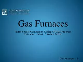
Gas Furnaces. North Seattle Community College HVAC Program Instructor – Mark T. Weber, M.Ed. Gas Furnaces - 1. Objectives. After studying this chapter, you should be able to: Describe each of the major components of a gas furnace

E N D
Gas Furnaces North Seattle Community College HVAC Program Instructor – Mark T. Weber, M.Ed. Gas Furnaces - 1
Objectives • After studying this chapter, you should be able to: • Describe each of the major components of a gas furnace • List two fuels burned in gas furnaces and describe characteristics of each • Discuss a multipoise furnace and its safety devices
Objectives (cont’d.) • Discuss flame rollout, auxiliary limit, and draft safeguard switches • Discuss gas pressure measurement in inches of water column and describe how a manometer is used to make this measurement • Discuss gas combustion • Describe a solenoid, diaphragm, and heat motor gas valve
Objectives (cont’d.) • List the functions of an automatic combination gas valve • Describe the function of a servo-operated gas pressure regulator • Discuss the meaning of a redundant gas valve • Discuss different gas burners and heat exchangers
Objectives (cont’d.) • Describe the difference between induced-draft and forced-draft systems • Describe and discuss different ways of controlling the warm air fan • State the function of an off-delay timing device for warm air fan control • Describe standing pilot, intermittent pilot, direct-spark, and hot surface ignition systems
Objectives (cont’d.) • List three flame-proving devices and describe the operation of each • Discuss the delay in starting and stopping the furnace fan • State the purpose of a limit switch • Describe flue-gas venting systems • Discuss flame rectification and how it pertains to local and remote flame sensing
Objectives (cont’d.) • Apply flame rectification troubleshooting and maintenance procedures • Discuss the components of a high efficiency gas furnace • Describe direct-vented, non-direct-vented, and positive pressure systems • Explain dew point temperature as it applies to a high-efficiency condensing furnace
Objectives (cont’d.) • Discuss excess, dilution, combustion, primary, and secondary air • Describe the condensate disposal system of a high-efficiency condensing gas furnace • Identify furnace efficiency ratings • Discuss electronic ignition modules and integrated furnace controllers
Objectives (cont’d.) • Describe two-stage furnace, modulating gas furnace, and variable output thermostat • Explain gas piping as it applies to gas furnaces • Interpret gas furnace wiring diagrams and troubleshoot flowcharts or guides • Compare the designs of a high-efficiency gas furnace and a conventional furnace
Objectives (cont’d.) • Describe the procedures for taking flue-gas carbon dioxide and temperature readings • Describe typical preventative maintenance procedures
Introduction to Gas-Fired, Forced-Hot-Air Furnaces • Heat-producing system • Consists of manifold, burners, ignition, controls, heat exchanger, and venting system • Heated air distribution system • Blower moves air throughout ductwork and ductwork assembly
Types of Furnaces • Include: • Upflow: stands vertically, top air discharge • “Low-boy”: used for little headroom • Downflow: stands vertically; bottom air discharge • Horizontal: positioned on its side • Multipoise or multipositional: can be installed in any position
Types of Furnaces (cont'd.) Figure 31-2 The airflow for an upflow gas furnace
Types of Furnaces (cont'd.) Figure 31-3 (B) The airflow for a low-boy for the more common upflow applications but can be changed furnace. The low profile of the low-boy is accomplished by placing the blower behind the furnace in a separate cabinet rather than in line with the heat exchanger
Types of Furnaces (cont'd.) Figure 31–4 The airflow for a downflow, or counterflow, gas furnace.
Types of Furnaces (cont'd.) Figure 31-5 (B) The airflow for a horizontal gas furnace Figure 31-5 (B) The airflow for a horizontal gas furnace
Gas Fuels • Natural gas • 90-95% methane and other hydrocarbons • Lighter than air (specific gravity = 0.60) • Colorless, odorless, and not poisonous • Displaces oxygen and can lead to suffocation • Odorants are added for detection purposes • Produces about 1050 Btu per cubic foot when burned with air
Gas Fuels (cont'd.) • Liquefied petroleum • Liquefied propane, butane, or a combination of both: keep under pressure until used • Propane produces 2500 Btu/ft³ but requires 24ft³ of air • Heavier than air (specific gravity = 1.52) • Displaces oxygen; can explode when accumulated • Butane produces 3200 Btu/ft³ • Difficult to work with, not very popular
Gas Fuels (cont'd.) • Manifold pressures • Expressed in inches of WC • 1 psi = 27.7 in. WC • Some common manifold pressures: • Natural gas and propane/air mixture: 3 to 3.5 in. WC • Manufactured gas: 2.5 in. WC • LP gas: 11 in. WC Figure 31-10 A manometer used for measuring pressure in inches of water column. Courtesy Ferris State University. Photo by John Tomczyk.
Gas Fuels (cont'd.) Figure 31-12 A digital manometer being used to measure gas pressure in inches of water column Courtesy Ferris State University. Photo by John Tomczyk
Gas Combustion • Requires fuel, oxygen, and heat • Ignition temperature for natural gas is 1100-1200ºF • Perfect combustion produces carbon dioxide, water vapor, and heat • Poor combustion produces carbon monoxide, soot, and other products • Flame should be blue with orange tips • Yellow tips indicate carbon monoxide
Gas Combustion (cont’d.) Figure 31-13 (A) Primary air is induced into the air shutter by the velocity of the gas stream from the orifice. (B) Ignition of the gas is on top of the burner. (C) Incomplete combustion yields yellow “lazy” flame. Any orange color indicates dust particles drawn in with the primary air
Gas Combustion (cont’d.) • Only gas pressure and primary air can be adjusted in the field • Gas/air mixture is important • 0-4% natural gas will not burn; 4-15% natural gas will burn but can explode; 15-100% natural gas will not burn or explode • Limits of flammability vary for gases • Extra primary air supplies better combustion
Gas Regulators • Drop gas pressure to proper level; maintain constant pressure at the outlet where gas is fed to the gas valve • Many regulators can be adjusted • LP regulators are located at supply tank • Always consult manufacturer's specifications when setting or adjusting gas regulators
Gas Regulators (cont'd.) Figure 31-15 The diagram of a standard gas pressure regulator
Gas Valve • Gas is piped from regulator to gas valve at manifold • Several types exist Figure 31–16 Natural gas installation where the gas passes through a separate regulator to the gas valve and then to the Manifold. Courtesy Cengage Learning 2013
Solenoid Valve • Normally closed (NC) • Electrical current applied to coil pulls spring-loaded plunger to open the valve Figure 31–18 A solenoid gas valve in its normally closed position. Courtesy Cengage Learning 2013
Diaphragm Valve • Uses gas pressure on one side of the diaphragm to open the valve • Types: • Electrically operated magnetic diaphragm valve; thermally operated diaphragm gas valve • When electric current is applied, gas is allowed to bleed off from upper chamber; gas pressure below diaphragm pushes valve open
Figure 31–23 When an electric current is applied to the leads of the bimetal strip heater, the bimetal warps, closing the valve to the upper chamber, and opening the valve to bleed the gas from the upper chamber. The gas pressure is then greater below the diaphragm, pushing the valve open. Courtesy Cengage Learning 2013 Figure 31–21 When an electric current is applied to the coil, the valve to the upper chamber is closed as the lever is attracted to the coil. The gas in the upper chamber bleeds off to the pilot, reducing the pressure in this chamber. The gas pressure from below the diaphragm pushes the valve open. Courtesy Cengage Learning 2013
Heat Motor-Controlled Valve • When heat is called for, a rod attached to the valve is heated and expands or elongates, causing the valve to open • 20 seconds to open; 40 seconds to close Figure 31–24 A heat motor–operated valve, (A) closed and (B) open. Courtesy Cengage Learning 2012
Automatic Combination Gas Valve • Used in many modern gas furnaces • Include manual control, pilot supply, pilot adjustment and safety shutoff, pressure regulator, main gas valve controls • Valves with dual shutoffs: redundant gas valves • Standing pilot automatic gas valves • Pilot burner is lit all the time; manual • Have safety shutoff features
Automatic Combination Gas Valve (cont'd.) • Intermittent pilot automatic gas valves • Pilot light is lit when there is a call for heat; when the call ends, the pilot goes out • Do not use power units or thermocouples; just two automatic valves: • Solenoid operated valve opens to permit passage of pilot gas • Servo operated valve opens to permit passage of gas for main burner operation
Automatic Combination Gas Valve (cont'd.) • Direct burner automatic gas valves • Electronic module or IFC lights the main burner directly, without a pilot flame • Ignition is accomplished by a spark, hot surface igniter, or glow coil • No power units or reset buttons • Two automatic valves are energized on a call for heat • Slow-opening is used when two automatic gas valves are used
Other Furnace Parts • Manifold • Pipe through which gas flows to burners • Attached to the outlet of the gas valve • Orifice • Precisely sized hole in the spud • Allows correct amount of gas into burner • Burners: where combustion takes place • Require primary/secondary air in correct quantities
Heat Exchangers • Provide rapid heat transfer from the combustion products to the air that will be distributed in the space to be heated • Must have correct airflow • Many sizes, shapes, and materials Figure 31–39 A heat exchanger with four sections. Courtesy Cengage Learning 2013
The Fan Switch • Automatically turns the blower on/off • Can be temperature controlled or on a time delay • Blower activation and shutoff are delayed • Gives heat exchanger time to heat up at the beginning of the cycle and cool off at the end of the heating cycle
The Limit Switch • Safety device that closes the gas valve if the heat exchanger overheats • High-limit cut-out requirements vary, but are often between 200°F and 220°F • Fan switch and limit switch can be combined into a single unit • Can be high-voltage, low-voltage, or combo • Controlled by the same bimetal helix • May be automatic or manual reset devices
Pilots • Small burners used to ignite the gas burner on conventional gas furnaces • May be aerated or nonaerated • Standing pilots burn continuously; other pilots are ignited by an electric spark or other ignition device when the thermostat calls for heat • Pilot flame provides heat for safety devices that shut off gas flow if the pilot goes out
Safety Devices at the Standing Pilot • Flame-proving devices prevent gas from flowing through the valve if pilot is out • Thermocouples and thermopiles • Pilot heats hot junction of thermocouple and keeps it open so gas can flow • Thermopile: thermocouples wired in series • Bimetallic safety device: bimetal strip heated • Liquid-filled remote bulb • Pilot heats liquid, causing diaphragm to expand
Ignition Systems • Can ignite the pilot or main burner • Intermittent pilot ignition • Spark from electronic module ignites pilot, which ignites main burner • Pilot burns only when thermostat calls for heat • Natural gas: pilot valve remains open (not 100% shutoff) • LP gas: pilot valve will close if pilot does not light
Ignition Systems (cont'd.) • Direct spark ignition (DSI) • No pilot is used • Sensor rod sends signal through flame rectification to DSI module to confirm firing • Hot surface ignition • Uses silicon carbide placed in gas stream • Igniter is allowed to get very hot before gas valve opens: immediate ignition
Flame Rectification • Uses the flame as a switch • Flame located between two electrodes completes the rectification circuit • Rectification circuit converts AC power to DC, which tells the furnace to open the gas valve
High-Efficiency Gas Furnaces • Reduce outdoor air infiltration and room depressurization • Have multiple heat exchangers, flue-gas condensate disposal system, and induced or forced power drafted venting system • Operate below the dew point temperature of the combustion gases • As excess air decreases, DPT increases
High-Efficiency Gas Furnaces (cont'd.) • Annual fuel utilization efficiency rating (AFUE) allows consumer to compare furnace performance before buying • Furnace efficiency ratings are determined by amount of heat transferred to the heated medium • Conventional furnace: 78-80% AFUE • Mid-efficiency furnace: 78-83% AFUE • High-efficiency furnace: 87-97% AFUE
Electronic Ignition Modules and Integrated Furnace Controllers • Control the ignition and sequence of operations in most modern gas furnaces • 100% shutoff system • Both pilot/main gas valve shut down in failure • Non-100% shutoff system • Main gas valve shuts down; pilot continues to bleed gas • Continuous retry with 100% shutoff • 90-sec trial for ignition
Electronic Ignition Modules and IFCs (cont'd.) • Lockout: time period to light or relight the pilot or main burner • Soft: semi-shutdown but module will keep trying to relight the system • Hard: full shutdown; module must be reset • Prepurge, interpurge, and post-purge periods allow blower motor to clear heat exchanger • IFC provides sequence schemes
Electronic Ignition Modules and IFC (cont'd.) • Terminal marking abbreviations: • MV, PV, MV/PV, GND, 24V, 24V(GND), TH-W, IGNITER/SENSOR, SENSE, SPARK • Smart valve is gas valve and electronic control module in one • Pulse furnace ignites small quantities of gas many times per second in a closed combustion chamber
Two-Stage Gas Furnaces • Use a two-stage gas valve and a two-speed combustion motor with two pressure switches • First stage puts out manifold pressure of 1.75 in. WC and operates at 50-70% of total heating output • Second stage puts out manifold pressure of 3.5 in. WC and 100% of total furnace output
Modulating Gas Furnaces • Follows the heat loss of the structure, reducing cycling for greater efficiency • Determines exact heating requirements for the space and adjusts to changes • Optimizes furnace performance • Utilizes variable speed blowers
Venting • In conventional gas furnaces • Use convection to vent flue gases but lose heat to prevent corrosive condensation • Use Type B vent; approved masonry materials • In high efficiency gas furnaces • Recirculate gases to retain heat • Use small fans and plastic pipe • Category specifies correct amount of excess air