Download
1 / 26
260 likes | 437 Vues
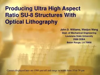
Deep UV-Blocking Particle Filter Using High Aspect Ratio Si Nanogratings with Smooth Sidewalls. Pran Mukherjee, Thomas H. Zurbuchen, L. Jay Guo, and Fred A. Herrero. Outline. Introduction to Application Summary of Fabrication Techniques Review of NIL/DRIE Technique Conclusion.

E N D
Deep UV-Blocking Particle Filter Using High Aspect Ratio Si Nanogratings with Smooth Sidewalls Pran Mukherjee,Thomas H. Zurbuchen, L. Jay Guo, and Fred A. Herrero
Outline • Introduction to Application • Summary of Fabrication Techniques • Review of NIL/DRIE Technique • Conclusion From standard Bosch (left) to first-run modification (middle) to current process (right) Sneak Peak!
The Solar Corona Solar Eclipse Composite Sensor Image The solar wind is a hail of charged and neutral particles ejected from the Sun.
Lyman-alpha The Solar Spectrum Lyman-alpha 103 1200-1270 Angstroms
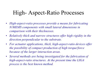
Primary Application: UV filter • Requirements: • block energetic photons, particularly Lyman-alpha UV at 121.6 nanometers • high geometric transparency to allow atoms through • high aspect ratio to collimate atoms • self-supported
Transmission of Ly-alpha Target Features
Transmission of Particles • Modeled solid sheet of 15000 angstroms Si • Grating should be ~30-50% open area, so double penetration depths • Atoms <15-20 keV/nucleon stopped; solar wind ranges from 1-2 keV/nucleon.
Applications and Technologies • Applications • Deep UV photon filters transparent to particles • Collimators for particle detectors • Polarizers • High aspect ratio molds • Broad-spectrum pushbroom sensor • Technologies • Thin silicon membrane • Boron doping and EDP etch • SOI wafer and dry etch • Grating Etch • Femtosecond laser • 2 micron lithography and electroplating • Nanoimprint lithography and deep RIE Double-sided membrane processing!!
Fabrication Techniques • Three techniques attempted • Femtosecond laser etch • Optical lithography • Nanoimprint lithography with DRIE • Constraints • Grating etch time • Grating line width • Aspect ratio • Sidewall straightness
Femtosecond Laser Etch Joglekar, et al., Proc. Natl. Acad. Sci. 101(16), 5856–5861, 2004 • Laser energy profile allows submicron etching at material damage threshold • Lower energy makes smaller holes, but need more shots in both length and depth dimensions to make trenches • 1kHz laser would take 12 years to etch 2cm square grating! • 10MHz and faster lasers becoming available
Optical lithography • Ion implant etch stop • 2-micron frontside features of varied lengths • Combination DRIE/EDP backside etch • Sputter and electroplate Au • 30 micron long lines look perfect • Lines longer than 60 microns have stiction problems; these are 420 microns long
Nanoimprint and DRIE Sample pre-eched to 500nm with 500nm oxide • 15 min STS etch • 12:1 aspect ratio • <10nm scalloping • 400nm features
Mold with 50% duty cycle MRI8030 Chrome SiO2 Si Nanoimprinting (1) • Make or buy SOI wafer • Grow 200 nm mask oxide • Evaporate 10nm chromium • Deposit thermal polymer (MRI 8030) • Nano-imprint grating into polymer Steps 1-4 Step 5
Nanoimprinting (2) • Polymer residual etch, chromium etch • Dry-etch mask oxide MRI8030 Chrome SiO2 Si
Grating Etch (1) • STS etch grating, stage 1 • 7 minute STS etch • 8.5:1 aspect ratio • slight roughness • 150nm features • 35nm mask undercut • 0.18 m/min etch
Grating Etch (2) • Concerns • Controllability of oxidation must be within 10nm • Oxide stress • Aspect ratio of mask slowing or stopping second-stage etch • Stopping on buried oxide without widening lines • Dry oxidize sample to narrow grating lines and create second-stage etch mask • STS etch to oxide layer etch-stop
Gas Ratio Characterization From standard Bosch (left) to first-run modification (middle) to current process (right)
Oxide Etch Characterization • 200nm oxide masks rapidly etched away • C4F8 passivation layer etches oxide, platen bias enhances effect • Oxygen content reduces Si etch rate by ~20x, but not oxide etch rate • Reducing platen bias reduces oxide-etch rate
Process Comparison • Bosch Process • Etch Step: 160 sccm SF6, 16 sccm O2, 12 seconds, 20W platen, 800W coil • Passivate: 85 sccm C4F8, 8 seconds, 0W platen, 800W coil • 20/15 mT base pressure for etch/passivation (set by valve angle) • Our Process • Etch Step: 20 sccm SF6, 75 sccm O2, 9 seconds, 150W platen, 550W coil • Passivate: 100 sccm C4F8, 3 sccm SF6, 12 seconds, 0W platen, 500W coil • 0.7 mT base pressure • Biggest differences • Absolute gas pressures • Percentage of oxygen in etch step • Ratio of etch/passivation times • Etch slows from 2-5 microns per minute to 0.2 microns per minute
Future Concerns • Fix undercutting in 100nm process • Double-etch process where oxidation of primary 100nm feature narrows lines and creates second-stage 50nm mask • Create crosshatched mold to avoid stiction • Back-etch • Plug pinholes in final grating
Nanoimprint and DRIE Process Mold with 50% duty cycle • Make or buy SOI wafer • Grow 200 nm mask oxide • Evaporate 10nm chromium • Deposit thermal polymer (MRI 8030) • Nano-imprint grating into polymer • Polymer residual etch, chromium etch • Remove polymer • Dry-etch mask oxide • STS etch grating, stage 1 • Dry oxidize sample to narrow grating lines and create second-stage etch mask • STS etch to oxide layer etch-stop MRI8030 Steps 1-4 Chrome SiO2 Si Step 5 Step 10 Step 6 Steps 7-8 Step 9 Step 11
2 micron feature characterization First try: 75 nm scallop Second try: ~30 nm scallop Third try: ~10 nm scallop Fourth try: <8 nm scallop
350 nanometer characterization • Required significant tweaking to reduce oxide mask etching, but we achieved ~7.5:1 aspect ratio gratings with ~7 nm scalloping and 350nm features