Buy Honeywell Limit switch
80 likes | 101 Vues
Buy Honeywell Limit switch from Indus corporation and use for Personnel Safety, Machine Safety, product detection, and Product Detection & Count. Get it now!<br><br>https://indusautomation.co/product-category/mini-limit-switc/

Buy Honeywell Limit switch
E N D
Presentation Transcript
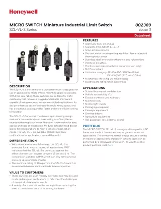
MICRO SWITCH Miniature Industrial Limit Switch SZL-VL-S Series 002389 Issue 3 Datasheet FEATURES • Approvals: CCC, CE, cULus • Sealed to IP67, NEMA 1, 12, 13 • Snap-action contacts • Die-cast metal housing with glass-filled, flame-retardant thermoplastic cover • Stainless steel levers with either steel and nylon rollers • Variety of actuators • Positive-opening contacts (side rotary version only) • RoHS compliant • Utilization category: AC-15 A300 (380 Vac/0.5 A) DC-13 Q300 (220 Vdc/0.05 A) • Mechanical life rating: 10 million cycles • Electrical life rating: 0.5 million cycles DESCRIPTION The SZL-VL-S Series miniature-type limit switch is designed for use in applications where limited mounting space is available. With IP67 seal rating, these switches are suitable for OEM machinery that requires a rugged and reliable limit switch capable of being mounted in space restricted applications. Its design enhances ease of wiring with ample wiring space, and has an optional cable gland for faster and more efficient wiring termination. APPLICATIONS • Scissor/boom position detection • Vehicle accessibility lifts • Escalators/Motorized walkways • Machine tools • Mobile light towers • Packaging equipment • Conveyor equipment • Overhead doors • Agriculture equipment • Rail passenger cars (internal doors) The SZL-VL-S Series switches have a split-housing design made of a die-cast body and head with glass-filled, flame- retardant thermoplastic cover. The cover is removable for easy access and ease of installation. Modular actuator head design allows for configurations to meet a variety of application needs. The SZL-VL-S are available globally and carry certifications for applications around the world. PORTFOLIO The MICRO SWITCH SZL-VL-S series joins Honeywell’s NGC Series and the GLL Series switches for general industrial applications. The combined portfolio helps ensure a variety of industrial applications or position sensing tasks can be performed by a Honeywell limit switch. To view the entire product portfolio, click here. DIFFERENTIATION • With robust environmental ratings, the SZL-VL-S is protected for all kinds of industrial applications. IP67 indicates that the SZL-VL-S is protected against the effect of immersion in water between 15 cm and 1 m. The competition standard is IP65 which can only withstand low pressure spray and jets of water. • The electrical rating of 10 A permits the SZL-VL-S switch to be used with heavier electrical loads than competitors VALUE TO CUSTOMERS • These switches are user-friendly interfaces and may be used in a broad range of applications to help meet the challenges of many industrial environments. • A variety of actuators fit on the same platform reducing the need to use various kinds of mounting hardware.
MICRO SWITCH Miniature Industrial Limit Switch, SZL-VL-S Series Table 1. Performance Specifications Characteristic Description Approvals Parameter Miniature industrial limit switch CCC, CE, cULus Die-cast metal housing with glass-filled, flame-retardant thermoplastic cover UL 94 flame spread testing: V-0 rated Conduit entry or cable gland Snap-action (all versions) Positive-opening contacts (side rotary version only) Silver alloy AC-15 A300 (380 Vac/0.5 A) DC-13 Q300 (220 Vdc/0.05 A) 10 A/250 Vac (EN 60947-5-1) < 25 mOhm >100 MOhm at 500 Vdc 2500 Vdc 1890 Vac for metal housing, 1890 Vac between all terminals to enclosure after durability test < 10 mA 3 IP67 -20°C to 70°C [-4°F to 158°F] (with no icing) 95 %RH 30 G, conforming to IEC 60068-2-27 10 G, 10 Hz to 55 Hz displacement amplitude 0,75 mm, conforming to IEC 60068-2-6 (wobble excluded) 10M cycles @ 120 cpm max. 0.5M cycles @ 30 cpm max. under the rated resistance load 0,05 mm/s to 2 m/s (based on pin plunger limit switch) Mechanical: 120 ops/min; Electrical: 30 ops/min 120 g to 150 g Housing material Electrical connection Contact design Contact material Electrical ratings Thermal current (Ith) Initial contact resistance Insulation resistance Impulse voltage Dielectric voltage Leakage current Pollution degree Environmental sealing Operating temperature Humidity Shock Vibration MCTF (Mechanical life) MCTF (Electrical life) Operating speed Operating frequency Weight Figure 1. Circuitry Figure 2. Mounting Holes Figure 3. Wiring NO 3 4 NO 14,6 [0.57] 4X M5 NC 1 2 NC 56 [2.21] 16 [0.63] 21 [0.83] MICRO SWITCH SZL-VL-S Miniature Industrial Limit Switch Datasheet | sps.honeywell.com/ast | 2
MICRO SWITCH Miniature Industrial Limit Switch, SZL-VL-S Series Figure 4. Product Nomenclature – – – – SZL-VL S A N Customer Options1 Series SZL-VL Series Limit Switch Code Actuator Sealing Side rotary, fixed lever nylon roller, Ø18 x 6,5 Without M12 cable gland (blank) S N A Standard IP67 Side rotary, adjustable lever nylon roller, Ø18 x 6,5 With M12 cable gland M B Side rotary, adjustable rod Ø2,5 mm, 125 mm C D Top pin plunger Cross roller plunger Ø12,5 x 3,8 E Coil spring wobble with plastic rod F Steel wire wobble G 1 This special designator code consists of up to two alphanumeric characters, and is used to indicate s ome optional features such as customer code. Top roller plunger Ø12,5 x 3,8 H Side rotary, fixed lever steel roller, Ø18 x 6,5 I Side rotary, adjustable lever steel roller, Ø18 x 6,5 J Coil spring wobble K MICRO SWITCH SZL-VL-S Miniature Industrial Limit Switch Datasheet | sps.honeywell.com/ast | 3
MICRO SWITCH Miniature Industrial Limit Switch, SZL-VL-S Series Table 2. Order Guide mm [in] Operating force/torque Differential travel max. Min. travel to achieve positive opening Overtravel min. Pretravel max. Free position mm [in] mm [in] mm [in] (max.) Roller/pin plunger Nylon roller, Ø18 x 6,5 [Ø0.71 x 0.25] Steel roller, Ø18 x 6,5 [Ø0.71 x 0.25] Nylon roller, Ø18 x 6,5 [Ø0.71 x 0.25] Steel roller, Ø18 x 6,5 [Ø0.71 x 0.25] Catalog listing Actuator Lever Bar chart 18 Ncm [1.59 in-lb] 18 Ncm [1.59 in-lb] 18 Ncm [1.59 in-lb] 18 Ncm [1.59 in-lb] Side rotary, fixed lever SZL-VL-S-A-N-M Steel, R30 0° 25° 15° 70° 40° Side rotary, fixed lever SZL-VL-S-I-N-M Steel, R30 0° 25° 15° 70° 40° 40° 25° max. 1-2 Side rotary, adjustable lever ? ? SZL-VL-S-B-N-M Steel, R30 to R70 0° 25° 15° 70° 40° 3-4 3-4 1-2 95° max. 0° 10° max. Side rotary, adjustable lever SZL-VL-S-J-N-M Steel, R30 to R70 0° 25° 15° 70° 40° Metal rod, Ø2,5 mm [0.1 in], 125 mm [4.92 in] long 18 Ncm [1.59 in-lb] Side rotary, adjustable rod SZL-VL-S-C-N-M – 0° 25° 15° 70° 40° 27 ±0,8 [1.04 ±0.03]* 38,5 ±0,8 [1.5 ±0.03]* 38,5 ±0,8 [1.5 ±0.03]* Metal pin, Ø6,6 [0.26] 2 1,5 [0.06] 3,5 [0.14] 9 N SZL-VL-S-D-N-M Top pin plunger – n/a [0.08] [2.02 lb] 2 mm max. 1-2 Steel roller, Ø12,5 x 3,8 [Ø0.5 x 0.15] Steel roller, Ø12,5 x 3,8 [Ø0.5 x 0.15] ? ? Top roller plunger 2 1,5 [0.06] 3,5 [0.14] 9 N 3-4 SZL-VL-S-H-N-M – n/a 3-4 [0.08] [2.02 lb] 1-2 5,5 mm max. 0,5 mm max. 0 Top cross roller plunger 2 1,5 [0.06] 3,5 [0.14] 9 N SZL-VL-S-E-N-M – n/a [0.08] [2.02 lb] Ø5,8 mm [0.23 in] coil spring with plastic rod Ø5,8 mm [0.23 in] coil spring with Ø1,2 mm [0.05 in] metal wire Ø5,8 mm [0.23 in] coil spring Wobble, coil spring and nylon rod 2 N SZL-VL-S-F-N-M – 0° 30° – 20° n/a [0.45lb] 30° max. 1-2 ? ? Wobble, coil spring and metal wire 3-4 2 N 3-4 SZL-VL-S-G-N-M – 0° 30° – 20° n/a [0.45lb] 1-2 55° max. 10° max. 0° Wobble, coil spring 2 N SZL-VL-S-K-N-M – 0° 30° – 20° n/a [0.45lb] * (from the center of the mounting hole) MICRO SWITCH SZL-VL-S Miniature Industrial Limit Switch Datasheet | sps.honeywell.com/ast | 4
MICRO SWITCH Miniature Industrial Limit Switch, SZL-VL-S Series Dimensional Drawings • mm [in] Figure 5. SZL-VL Side Rotary Limit Switch (Fixed Lever) Figure 6. SZL-VL Side Rotary Limit Switch (Adjust. Lever) Ø 18 [0.7] roller 49,5 [1.95] 36 Ø 18 [0.7] roller [1.41] 5,2 [0.21] 44 PT 6,3 [0.25] [1.74] PT 6,3 [0.25] Adjustable length of arm 30 to 70 [1.18 to 2.76] R30 M4 arm fixing screw fixing screw M4 arm M4 arm fixing screw M6 arm fixing screw M4 arm fixing out 18,5 [0.73] 2X Ø 4,2 [0.17] mounting holes 18,5 [0.73] 12,5 [0.49] 2X Ø 4,2 [0.17] mounting holes 2X M5 (P = 0.8) tapped 7,0 [0.28] depth mounting holes 12,5 [0.49] 2X M5 (P = 0.8) tapped 7,0 [0.28] depth mounting holes 20 [0.79] 20 [0.79] 56 64 [2.21] 56 [2.52] 63,5 [2.5] [2.21] 64 2X M5 (P = 0.8) tapped mounting holes 73,20 [2.88] [2.52] 2 [0.08] 2X M5 (P = 0.8) tapped mounting holes 73,20 [2.88] 4 7,5 [0.30] 17 [0.67] 4 [0.16] [0.16] 7,5 [0.30] 17 [0.67] 21 25,7 [1.01] [0.83] 28,5 [1.12] 21 25,7 [1.01] [0.83] 28,5 [1.12] Figure 7. SZL-VL Side Rotary Limit Switch (Adjust. Rod) Figure 8. SZL-VL Pin Plunger Limit Switch 8,6 [0.34] 38,1 [1.5] Ø 2,5 [0.1] rod M6 mounting rod fastening screw with hexagonal holes 10 [0.39] Adjustable length of rod 30 to 118 [1.18 to 4.65] 6,6 [0.26] 3,5 [0.14] 2X Ø 4,2 [0.17] mounting holes 27 [1.06] 3,5 [0.14] 18,5 [0.73] 125 [4.92] 12,5 [0.49] 2X M5 (P = 0.8) tapped 7,0 [0.28] depth mounting holes 20 [0.79] 2X M5 (P = 0.8) tapped 7,0 [0.28] depth mounting holes 2X Ø 4,2 [0.17] mounting holes 20 [0.79] 63,5 [2.5] 56 [2.21] 56 64 [2.21] [2.52] 2X M5 (P = 0.8) tapped mounting holes 73,20 [2.88] 2X M5 (P = 0.8) tapped mounting holes 73,20 [2.88] 4 7,5 [0.30] 4 7,5 [0.30] 17 [0.67] [0.16] [0.16] 21 17 [0.67] 21 [0.83] 25,7 [1.01] [0.83] 28,5 [1.12] 25,7 [1.01] 28,5 [1.12] MICRO SWITCH SZL-VL-S Miniature Industrial Limit Switch Datasheet | sps.honeywell.com/ast | 5
MICRO SWITCH Miniature Industrial Limit Switch, SZL-VL-S Series Figure 9. SZL-VL Cross Roller Plunger Limit Switch Figure 10. SZL-VL Roller Plunger Limit Switch 10 [0.39] 10 [0.39] 3,8 [0.15] 3,8 [0.15] Ø 12,7 [0.50] Ø 12,7 [0.50] 15 [0.59] 38,5 [1.52] 2X Ø 4,2 [0.17] mounting holes 38,5 [1.52] 2X Ø 4,2 [0.17] mounting holes 2X M5 (P = 0.8) tapped 7,0 [0.28] depth mounting holes 2X M5 (P = 0.8) tapped 7,0 [0.28] depth mounting holes 63,5 [2.5] 56 [2.21] 63,5 [2.5] 64 56 64 [2.52] [2.21] [2.52] 2X M5 (P = 0.8) tapped mounting holes 73,20 [2.88] 73,20 [2.88] 2X M5 (P = 0.8) tapped mounting holes 4 7,5 [0.30] [0.16] 4 7,5 [0.30] 21 17 [0.67] [0.16] [0.83] 28,5 [1.12] 21 17 [0.67] 25,7 [1.01] [0.83] 28,5 [1.12] 25,7 [1.01] Figure 11. SZL-VL Coil Wobble (Plastic Tip) Limit Switch PT Figure 12. SZL-VL Coil Wobble (Wire Tip) Limit Switch 10,1 [0.4] 10,1 [0.4] 30 [1.18] PT Ø 1,2 [0.05] Ø 5,8 [0.23] 30 [1.18] Ø 5,8 [0.23] 100 [3.9] 100 [3.9] 20 [0.79] 20 2X Ø 4,2 [0.17] mounting holes [0.79] 2X Ø 4,2 [0.17] mounting holes 2X M5 (P = 0.8) tapped 7,0 [0.28] depth mounting holes 2X M5 (P = 0.8) tapped 7,0 [0.28] depth mounting holes 20 [0.79] 20 [0.79] 64 56 [2.2] 56 [2.2] 64 [2.52] [2.52] 73,20 [2.88] 73,20 [2.88] 2X M5 (P = 0.8) tapped mounting holes 2X M5 (P = 0.8) tapped mounting holes 4 7,5 [0.30] 17 [0.67] 7,5 [0.30] 17 [0.67] 4 [0.16] 21 [0.16] 21 [0.83] 28,5 [1.12] 25,7 [1.01] [0.83] 28,5 [1.12] 25,7 [1.01] MICRO SWITCH SZL-VL-S Miniature Industrial Limit Switch Datasheet | sps.honeywell.com/ast | 6
MICRO SWITCH Miniature Industrial Limit Switch, SZL-VL-S Series Figure 13. SZL-VL Coil Wobble Limit Switch Figure 14. SZL-VL M12 Cable Gland (A1-LSC-F) 10,1 [0.4] 8 Cable outer diameter Ø 4 to Ø 6,5 [Ø 0.16 to Ø 0.26] 5,2 [0.20] [0.31] Ø 16,8 [0.66] 30 [1.18] M12X1.5 Ø 5,8 [0.23] 100 [3.9] 15 12 [0.59] [0.47] 20 2X Ø 4,2 [0.17] mounting holes [0.79] 10,5 [0.41] 2X M5 (P = 0.8) tapped 7,0 [0.28] depth mounting holes 20 [0.79] 56 [2.2] 64 [2.52] 2X M5 (P = 0.8) tapped mounting holes 73,20 [2.88] 4 7,5 [0.30] [0.16] 21 17 [0.67] [0.83] 28,5 [1.12] 25,7 [1.01] MICRO SWITCH SZL-VL-S Miniature Industrial Limit Switch Datasheet | sps.honeywell.com/ast | 7
ADDITIONAL INFORMATION The following associated literature is available on the Web at sensing.honeywell.com: • Product installation instructions • Product range guide • Product application-specific information – Application Note: Mid-tier Limit Switch Product Introduction m WARNING PERSONAL INJURY DO NOT USE these products as safety or emergency stop devices or in any other application where failure of the product could result in personal injury. Failure to comply with these instructions could result in death or serious injury. m WARNING MISUSE OF DOCUMENTATION • The information presented in this product sheet is for reference only. Do not use this document as a product installation guide. • Complete installation, operation, and maintenance information is provided in the instructions supplied with each product. Failure to comply with these instructions could result in death or serious injury. Warranty/Remedy Honeywell warrants goods of its manufacture as being free of defective materials and faulty workmanship during the appli- cable warranty period. Honeywell’s standard product warranty applies unless agreed to otherwise by Honeywell in writing; please refer to your order acknowledgement or consult your local sales office for specific warranty details. If warranted goods are returned to Honeywell during the period of coverage, Honeywell will repair or replace, at its option, without charge those items that Honeywell, in its sole discretion, finds defec- tive.The foregoing is buyer’s sole remedy and is in lieu of all other warranties, expressed or implied, including those of merchantability and fitness for a particular purpose. In no event shall Honeywell be liable for consequential, special, or indirect damages. FOR MORE INFORMATION Honeywell Advanced Sensing Technologies services its customers through a worldwide network of sales offices and distributors. For application assistance, current specifications, pricing or the nearest Authorized Distributor, visit our website or call: USA/Canada +1 302 613 4491 Latin America +1 305 805 8188 Europe +44 1344 238258 Japan +81 (0) 3-6730-7152 Singapore +65 6355 2828 Greater China +86 4006396841 While Honeywell may provide application assistance personally, through our literature and the Honeywell web site, it is buyer’s sole responsibility to determine the suitability of the product in the application. Specifications may change without notice. The information we supply is believed to be accurate and reliable as of this writing. However, Honeywell assumes no responsibility for its use. Honeywell Advanced Sensing Technologies 830 East Arapaho Road Richardson, TX 75081 sps.honeywell.com/ast 002389-4-EN | 4 | 04/21 © 2021 Honeywell International Inc. All rights reserved.