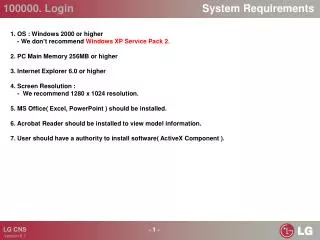
Electrical System Overview and Requirements
Electrical System Overview and Requirements. Block Diagram. PDU Latest Revision – Inside Look. Upper PDU Components. Temp controllers adjustment procedure. Temp. controllers IR Temp. controller Heating table Temp. controller. 1. 2. 4. Phase Contactors 55A

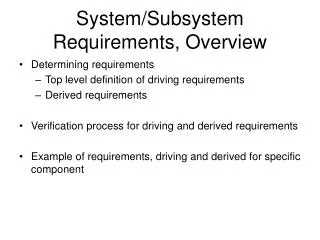
Electrical System Overview and Requirements
E N D
Presentation Transcript
Block Diagram Confidential
PDU Latest Revision – Inside Look Confidential
Upper PDU Components Temp controllers adjustment procedure • Temp. controllers • IR Temp. controller • Heating table Temp. controller 1 2 4 • Phase Contactors 55A • For the driversFor the IR 3 Confidential
Mid Level – Inside Look Circuit breaker 3 phase, 63A Lamps 220v Main Switch S1 Fuse holder Confidential
Lower Level-PDU Circuit breakers 2*6A 7*10A 2*16A Main filter 3 Phases UPS rotary switch Confidential
PDU – Main Safety Safety relay Confidential
PDU – Main Safety • Phase R starts the following loops: • Phase R UPS K1 • K1 is the Safety relay – Responsible for shutting down the motion system in case of emergency. • When the 24v loop is cut, emergency is active. Confidential
Open Cabinet – Old Revision Confidential
1 2 3 Upper PDU • We have the following parts: • Temperature Display / Control for the Heating Table. • Heating Hood Row Selection / OFF Switch • Heating Hood Zone Selection Switch Confidential
Mid Level PDU Heating Hood 3 Phase Magnetic Relay Here is where the computer turns on the heating. Power Pilot Lamps. (Right) Fuses for the Pilot Lamps (Left) Main Power Breaker Main Power Switch Confidential
Lower Level PDU Main Power Filter UPS / Main Selector Switch Surge / Spike Suppressor Circuit Safety System Relay Heating Table Relay Confidential
K3 RL3 New PDU (UL Certified) – Last Revision • New Safety Relay • New Safety relay K3 (the same relay type as used for activating the Drying System) for the drivers replaces the old problematic one. • The K3 relay has been moved to a new position, and the RL3 relay is installed into its place (see Figure 4). Confidential
Last PDU Revision (UL Certified) Confidential
Last PDU Revision (UL Certified) (Cont.) • New Main 3-phase Circuit Breaker • The main Circuit Breaker F1 (see green line) includes the Switch Tripped mechanism (terminals 9,10). The two phases are connected (see dashed green line) via the Emergency Switch. • When the Switch Tripped is powered, the F1 contacts are closed and the machine is connected to the power line. • When the Emergency Switch is pressed, the Switch Tripped will be powered off and the F1 contacts will be opened,(i.e. the machine will be disconnected from the power line). Confidential
Last PDU Revision (UL Certified) (Cont.) • New Emergency Stop Button • The new PDU is equipped with its own Emergency Stop button When pressed, the RL3 relay will be activated and the electrical power will be disconnected before the Main 3-phase Circuit Breaker and from the UPS to the machine – see Figure (next slide). Confidential
To UPS Main Safety – PDU Confidential
Main Safety – PDU • The green dash line marksthe circuit UPS Emergency Switch RL3 coil UPS. When the Emergency Switch is pressed, this circuit is open. • The cyan dot line specifies the circuitUPS RL3 contacts Drivers Left Cabinet(PC, Power Supplies) UPS. When the Emergency Switch is pressed, this circuit is open. • The magentadot line specifies the self-sustain loop for holding the RL3 powered in case of general electric failure(i.e. Switch Tripped is not powered and the green circuit is open). Confidential
PDU with Heating Control Unit (External or Built-in) Confidential
XL Premium – PDU Confidential
XL Premium – PDU • XL Premium printing table has an Extra 5 heating table elements (Total of 10 heating elements). • Circuit breaker on the PDU is changed from 16A to 20A in order to support it. • Controlling the heating tables is from the Printing table heating controller (F5 circuit breaker on the PDU) • Once the heating table gives signals that the current temperature is lowered then the desired temperature, a 24v input signal will operate the SSR and the heating table will work. Confidential
XL Premium – PDU 20A Circuit breaker Confidential