DESIGN PROCEDURE
The assembler is the system program that translate source code written in assembly language to object code( Machine Language) and other information for loader. DESIGN PROCEDURE. The following steps should be used to design an assembler : Specify the problem Specify data structures

DESIGN PROCEDURE
E N D
Presentation Transcript
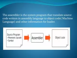
The assembler is the system program that translate source code written in assembly language to object code( Machine Language) and other information for loader.
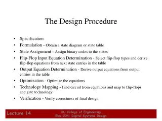
DESIGN PROCEDURE The following steps should be used to design an assembler : Specify the problem Specify data structures Define format of data structures Specify algorithm Look for modularity(i.e capability of one program to be subdivided into independent programming units ) Repeat 1 through 5 on modules
STATEMENT OF PROBLEM In this step assembler considers how to make the required information available. Consider the assembly statement MOVER BREG, ONE We must have the following information to synthesize the machine instruction corresponding to this statement: 1. Address of the memory word with which name ONE is associated, 2. Machine operation code corresponding to the mnemonic MOVER.
Data Structure for pass 1 The second step in our design procedure is to establish the databases that we have to work with. Pass 1 Data Structures 1. Input source program 2. A Location Counter (LC), used to keep track of each instruction’s location. 3. A table, the Machine-operation Table (MOT), that indicates the symbolic mnemonic, for each instruction and its length (two, four, or six bytes)
4. A table, the Pseudo-Operation Table (POT) that indicates the symbolic mnemonic and action to be taken for each pseudo-op in pass 1. 5. A table, the Symbol Table (ST) that is used to store each label and its corresponding value. 6. A table, the literal table (LT) that is used to store each literal encountered and its corresponding assignment location. 7. A copy of the input to be used by pass 2.
Data structures for pass2: A copy of source program input pass1 1. Location counter(LC) to keep track of location of each instruction. 2. Machine Operation Table(MOT) that indicates for each instruction i) symbolic mnemonic ii) length iii) binary machine opcode iv) format of instruction. 3. Pseudo Operation Table(POT) that indicates symbolic mnemonic and action to be taken for each pseudo op in pass2 4. Symbol table(ST) prepared by pass1,containing each label and its corresponding value.
5. Base Table(BT) that indicates which registers are currently specified as base registers and their contents. 6. Workspaces for a)holding various parts of instruction during assembling, b)producing a printed list 7. Storage for holding the copy of assembled instructions in the format needed by the loader
Format of database MOT: Format of machine operation table ‘b’ represents the “blank”
Algorithm : one pass Begin • read first input line • if OPCODE = ‘START’ then begin • save #[Operand] as starting addr • initialize LC to starting address • write line to intermediate file • read next line • end( if START) • else • initialize LC to 0 • While OPCODE != ‘END’ do • begin • if this is not a comment line then • begin • if there is a symbol in the LABEL field then • begin • search ST for LABEL • if found then
set error flag (duplicate symbol) • else • (if symbol) • search OPTAB for OPCODE • if found then • add 3 (instr length) to LC • else if OPCODE = ‘WORD’ then • add 3 to LC • else if OPCODE = ‘RESW’ then • add 3 * #[OPERAND] to LC • else if OPCODE = ‘RESB’ then • add #[OPERAND] to LC • else if OPCODE = ‘BYTE’ then • begin • find length of constant in bytes • add length to LC • end • else
set error flag (invalid operation code) • end (if not a comment) • write line to intermediate file • read next input line • end { while not END} • write last line to intermediate file • Save (LC – starting address) as program length • End {pass 1}
Algorithm : Two Pass • • Begin • read 1st input line • if OPCODE = ‘START’ then • begin • write listing line • read next input line • end • write Header record to object program • initialize 1st Text record • while OPCODE != ‘END’ do • begin • if this is not comment line then • begin •
search OPTAB for OPCODE • if found then • begin • if there is a symbol in OPERAND field then • begin • search ST for OPERAND field then • if found then • begin • store symbol value as operand address • else
begin • store 0 as operand address • set error flag (undefined symbol) • end • end (if symbol) • else store 0 as operand address • assemble the object code instruction • else if OPCODE = ‘BYTE’ or ‘WORD” then • convert constant to object code • if object code doesn’t fit into current Text record then • begin • Write text record to object code • initialize new Text record
end • add object code to Text record • end {if not comment} • write listing line • read next input line • end • write listing line • read next input line • write last listing line • End {Pass 2}
Modularity In the flowcharts for Pass 1 and Pass 2, we examine each step as a candidate for logical separation. The choices are identified in the shape: “name” is the name assigned to the function(MOTGET, PRINT) Function Name