Download
1 / 13
130 likes | 252 Vues
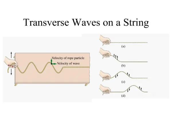
Conclusions on Transverse Shearing Stress Calculations. Maximum Value at Neutral Axis – IF CROSS-SECTION IS NOT NARROWER ELSEWHERE Depends on Shape of Cross Section (Table 4.3) Equal to Zero at Top and Bottom Boundaries Important for Short Beams Wood Beams – if span/depth < 24

E N D
Conclusions on Transverse Shearing Stress Calculations • Maximum Value at Neutral Axis –IF CROSS-SECTION IS NOT NARROWER ELSEWHERE • Depends on Shape of Cross Section (Table 4.3) • Equal to Zero at Top and Bottom Boundaries • Important for Short Beams • Wood Beams – if span/depth < 24 • Metal Beams with Thin Webs- if span/depth<15 • Metal Beams with Solid Section-if span/depth<8
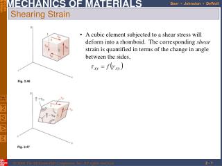
Summary of Stress Analysis Procedure in Symmetrical Beams • Find Centroid of Crosss-Section Neutral Axis (Table 4.2) • Choose x-y-z Ref. System Centered at Centroid • Normal Bending Stress • Zero at neutral axis • Max. at top and/or bottom surface • Transverse Shear Stress • Zero at top and bottom edge • Max. at neutral axis unless cross-section is narrower elsewhere • Z(y=y1)=width of cross-section where shear stress is calculated yA = Moment of area above y=y1 with respect to neutral axis
Summary of Solutions to Textbook Problems • Problem 4-7: Cantilever beam subjected to biaxial bending. Use superposition of maximum stresses at critical point: • Max. Bending Stress =26,122+22,857=48,979psi • Expect failure by yielding since SY =43,000 psi for AISI 1020 annealed carbon steel (Table 3.3) • Problem 4-8: Beam with fixed ends subjected to concentrated force at mid-span, and circular cross-section of diameter equal to 1 in. • Check for possible failure by yielding, using Case 6 in Table 4.1, to obtain: max=(600)(0.5)/0.0491=6110 psi, which is smaller than SY=51,000psi for AISI 1020 cold drawn steelno yielding failure • Check for failure due to force-induced deformation, using Table 4.1 to obtain: ymax=0.0098>0.005inches design is NOT approved
Summary of Solutions to Textbook Problems (Continued) • Problem 4-9: Thin plate subjected to tension and temperature change • Check for failure by yielding at max. temperature: not predicted since max=17,500/[(0.0625)(3)]=93,333psi, whereas SY=101,000 psi for Ti-6Al-4V alloy at 4000F (see Table 3.5) • Check for failure by force-induced deformation: NOT predicted since f=fL0=(93,333/16x106)(20)=0.1167”<cr=0.1250”, where E=16x106psi is found for Titanium in Table 3.9 • Check for failure by temperature induced elastic deformation: NOT predicted since t=L0T=(20)(5.3x10⁻⁶)(325)=0.0345”<0.1250”, where the CTE, , is found from Table 3.8 for the Ti-6Al-4V alloy. • Failure OCCURS due to superposition of f+t=0.1512>specified limit of 0.125” • Problem 4-10: Submit solution for yielding failure only, i.e., ignore for now the presence of the cracks
Summary of Solutions to Textbook Problems (Continued) • Problem 4-14: Cylindrical boss fixed at one end and loaded by force “F” at free end • Critical points for bending and transverse shear • Infinitesimal volume elements at critical points • Calculate maximum stress components, x=347 Mpa, and xz=zx=(4/3)(F/A)=173 Mpa, according to Table 4.3 for solid circular section • No failure by yielding for uniaxial tensile stress, since Syp=351.7 Mpa for cold-rolled AISI steel in Table 3.3 • Distortion energy theory of failure is required for the multi-axial state of stress associated with transverse shear • Problem 4-15: Submit solution ONLY for failure modes associated with uniaxial state of stress