Understanding Computer Arithmetic: Unsigned and Signed Notations
This chapter provides a comprehensive overview of computer arithmetic, focusing on unsigned and signed notations. It explains non-negative representation, the significance of the most significant bit, and the ranges of values in both unsigned and two's complement formats. The chapter covers arithmetic operations including addition, subtraction, and multiplication, highlighting potential overflow issues and various algorithms like Booth's for multiplication. It also introduces Binary Coded Decimal (BCD) representation and discusses special arithmetic hardware and floating-point numbers, offering insights into their formats and operations.

Understanding Computer Arithmetic: Unsigned and Signed Notations
E N D
Presentation Transcript
Chapter 8 Computer Arithmetic
8.1 Unsigned Notation • Non-negative notation • It treats every number as either zero or a positive value • Range: 0 to 2n-1 • Unsigned Two’s Complement • Negative numbers have a 1 as the most significant bit and positive number (or zero) have 0 as the leading bit. • Range: -2n-1-1 to 2n-1-1 • Refer to Table 8.1
8.1 Unsigned Notation(continued) • Addition and Subtraction(Figure 8.1)
8.1 Unsigned Notation(continued) • Arithmetic overflow in addition • In non-negative notation, carry bit can set an overflow flag. • In two’s complement notation an overflow can occur at either end of the numeric range. (Figure 8.2)
8.1 Unsigned Notation(continued) • Arithmetic overflow in subtraction • X-Y is implemented as X+(-Y) • Y is converted to -Y by taking it’s two’s complement. • Implementation of micro-operation SUB: XX-Y (Figure 8.3)
8.1 Unsigned Notation(continued) • Overflow generation in unsigned two’s complement subtraction (Fig. 8.4) • The result should be larger than or equal to zero.
8.1 Unsigned Notation(continued) • Multiplication • A simple algorithm for xy Z =0 For I=1 to y do { z = z+x } • Shift-add multiplication • Partial products
8.1 Unsigned Notation(continued) • Multiplication • another simple algorithm for xy • The result in two n-bits registers, V.U U =0 For I = 1 to n do { IF Y0= 1 then CU = U +X; linear shift right CUV; circular shift right Y } • Refer to table 8.2 • RTL code for realize the algorithm • Refer to Table 8.3 • Hardware implementation (Refer to Figure 8.5)
8.1 Unsigned Notation(continued) • Multiplication • Booth’s algorithm (Figure 8.6) • This algorithm works directly on two’s complete numbers. • UV X*Y U =0; Y-1 = 0; For I=1 To n DO {IF start of a string of 1’s in Y THEN U = U-X; IF end of a string of 1’s in Y THEN U =U+X; Arithmetic shift right UV; Circular shift right Y AND copy Y0 to Y-1}
Division • Z = X Y • Z = 0; WHILE x y DO { z = z + 1, x = x-y }
Division(continued) • Shift-subtract division of two binary values. • Dividend: UV, divisor: X, quotient: Y, remainder: U • IF U X THEN exit with overflow; Y = 0; C = 0; FOR i = 1 TO n DO { linear shift left CUV; linear shift left Y; IF CU X THEN {Y0 = 1, U = CU -X } }
Division(continued) • Non-restoring division algorithm • Re-storing division algorithm
How to compare U and X • Figure 8.8
Figure 8.9 Hardware implementation of restoring algorithm
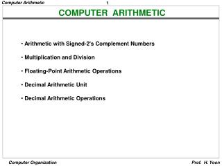
8.2 Signed Notations • Signed-magnitude • Signed-two’s complement • To add and subtract two signed-two’s complementation values, we simply treat the sign bit as the most significant bit of magnitude. • Multiplication can be accomplished by using Booth’s algorithm
8.3 Binary Coded Decimal • BCD Format: 4 bits can represent one decimal digit. • Addition and subtraction (Figure 8.13) • We adjust the hardware that adds numbers to account for the BCD representation. • When the sum of two digits is more than 9, adding 6 to the result generated by a binary adders produces the correct result.(Figure 8.11) • Nine’s complement (Figure 8.12) or ten’s complement can be used for subtraction.
Figure 8.13
8.4 Special Arithmetic Hardware • Pipelining • Arithmetic pipeline (Figure 8.14) • To increase the throughput, the numbers of results generated per time unit. • Speed up: a metric used to measure the performance of a pipeline.
8.4 Special Arithmetic Hardware(continued) • Pipelining The maximum speedup • Lookup table (Figure 8.15 and 8.16)
8.4 Special Arithmetic Hardware(continued) • Carry-save adder(Figure 8.17) • Wallice Tree: a combinatorial circuit used to multiply two numbers.(Figure 8.18)
Example X * Y X = 111 Y = 110 ----- 000 PP0 111 PP1 111 PP2 ------- 101010 Final sum calculated
Example X * Y (6-bit) X = 1011 Y = 1110
Figure 8.21 An 8X8 Wallice Tree Multiplier
8.5 Floating Point Numbers • Number format • Normalized • NoN Not a number • Biasing • Numeric characteristic • Precision • Gap • Range • Rounding • Guard bit