Download
1 / 28
290 likes | 627 Vues
C-band Structures at SPARC and Overview of C-band Technology at other International Projects. D. Alesini (LNF-INFN, Frascati, Italy). OUTLINE. WHY C-BAND FOR ACCELERATORS? C-BAND @ SPARC C-BAND ACCELERATORS OVERVIEW (PSI , SCSS) AND C-BAND TECHNOLOGY NEXT STEP:

E N D
C-band Structures at SPARC and Overview of C-band Technology at other International Projects D. Alesini (LNF-INFN, Frascati, Italy)
OUTLINE • WHY C-BAND FOR ACCELERATORS? • C-BAND @ SPARC • C-BAND ACCELERATORS OVERVIEW (PSI, SCSS) AND C-BAND TECHNOLOGY • NEXT STEP: • -STRONG DAMPED C-BAND ACCELERATING STRUCTURES: ELI_NP • -C-BAND GUN DESIGN AND FULL C-BAND LINAC
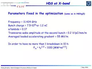
WHY C-BAND FOR ACCELERATORS? We refer to high gradient room temperature pulsed electron LINACS with typical parameters: 10-100 Hz rep. rate, 0.5-5 s RF pulse length, single/multi bunch, 20-100 MV/m average accelerating gradients. S-BAND (2.856 GHz) X-BAND (12 GHz) C-BAND (5.712 GHz) frequency NLC-CLIC projects: 0.5-1 m long sections up to 100 MV/m acc. gradient SLAC LINAC 3 m long sections 3.1 km total accelerator length 960 accelerating structures up to 50 GeV electron energy 20 MV/m average acc. gradient Accelerating gradient (f1/2) Dipole wakefield intensity (f3) Complication in fabrication technology Available commercial components
C-BAND ACCELERATING SYSTEM @ SPARC The energy upgrade of the SPARC photo-injector at LNF-INFN from 150 to more than 240 MeV will be done by replacing a low gradient S-Band accelerating structure with two C-band structures. The structures are TW and CI, have symmetric axial input couplers and have been optimized to work with a SLED RF input pulse. In the SPARC photoinjector the choice of the C-band for the energy upgrade was dictated by the opportunity to achieve a higher accelerating gradient, enabled by the higher frequency, and to explore a C-band acceleration combined with an S-band injector that, at least from beam dynamics simulations was very promising in terms of achievable beam quality. 2 structures 1.4 m long >35 MV/m acc. Gradient Design and built @ LNF SLED-SKIP RF compression system (IHEP, Beijing) Low gradient S-Band structure 13 MV/m S-Band SLAC-type structure 22 MV/m S-Band gun 120 MV/m
Design of C-Band TW structures for SPARC (D. Alesini, et al, JINST, 8, P05004, 2013) Structure design criteria: -CONSTANT IMPEDANCE (all equal irises) to simplify thefabrication and to reduce the unbalance between the accelerating field at the entrance and at the end of the structure, due to the combination of power dissipation along the structure and SLED pulse profile. -Large irises with elliptical shape to -reduce the peaksurface fieldobtaining at the same time an average accelerating field >35 MV/m with the available power from the klystron; -reduce the filling time of the structure and, consequently, the RF input pulse length thus reducing the breakdown rate; -reduce the dipole wake intensity -increase the pumping speed. -WAVEGUIDE COUPLER design based on “low pulsed heating” couplers for high gradient operation of X Band structures (SLAC). TIARA/FP7 EU funding
Test at high power (@KEK) of the prototype The high-power test started on November 5, 2010 and was completed on December 13, 2010. For almost one month of processing, from November 5 until December 2, more than 108 RF pulses of 200 ns width were sent into the structure with a repetition rate of 50 Hz. For a couple of days the RF pulse length was changed to 300 ns and for one day (November 12) the repetition rate was decreased to 25 Hz. On November 15, SKIP was switched on. After the high power test the structurehasbeencut in slicesfor an internalinspection. Wehaveidentified the signs of craters and dischargesmainly in the first acceleratingcellafter the input coupler, asexpected, because the highestfieldvalues are excitedat the beginning of CI structures.
FINAL C-BAND STRUCTURES First fabricated C-band structure (D. Alesini, et al, JINST 8, P10010, 2013)
Main PROBLEMS ENCOUNTERED IN THE STRUCTURE FABRICATION The main problems were related to the fact that we do not have a vertical >1.5 m long oven for brazing and we had to braze the structures in several steps. Each brazing step is a structure “stress”, requires a full control of the process and introduces unknowns since the success of the brazing cannot be guarantee at 100% even with a long experience. The design, machining and brazing of a new (complicated) structure (such as the SPARC C-band structures), require a strong activity of R&D and prototyping at least in the first phase to investigate all possible criticalities (RF, mechanical). For the SPARC C-band structures, we have fabricated only one small prototype before starting the construction of the first complete structure and this is the reason why we had to re-machine and re-cut the first structure a couple of time. In other words the first structure has been a prototype. At LNF-INFN this experience has been the first experience of a complete in-house design, realization and test of a such long multi-cell TW structure. We gain a lot (a lot) of experience thanks to this work. OK First realization technique New design of the junction, re-machining and brazing
C-BAND HIGH POWER STATION @ SPARC The new C-band power station will consist mainly of: • C-band klystron, manufactured by Toshiba Ltd (JP) • Pulsed HV modulator supplied by ScandiNova (S) • WR187 waveguide system with double resonator pulse compressor. • 500 W solid state klystron driver supplied by MitecTelecom (CDN) Toshiba ET37202 klystron and solid state modulator by Scandinova Test stand for high power test
C-BAND STRUCTURES: HIGH POWER TEST BENCH @SPARC From KLY Ceramic windows and power splitter RF pickup FW-RW RF Pickup TRANS Ion pumps C-Band structure RF Loads
C-Band SLED LOW POWER MEASUREMENTS The SKIP SLED has been fabricated in IHEP (Beijing). It has been fixed to the SPARC experimental hall ready for waveguide connection.
HIGH POWER TEST @SPARC: RESULTS (1/2) 1) The RF conditioning has been done in three steps: test of the Klystron system terminated into a loads test of the waveguide system up to the SPARC hall terminated into a load test of the first accelerating structure 2)The high power test on the first C-band structure started on Nov. 2013. We operated at 10 Hz with the nominal pulse width of 165 ns (slightly longer than the filling time of the structure). 3)We progressively increased the power from the klystron (increasing the HV of the modulator) monitoring: the current absorption of the 4 ion pumps (3 connected to the structure and 1 to the waveguide); the RF signals from pickups. Typical event of discharge Control panel RF reflected RF transmitted RF forward
HIGH POWER TEST @SPARC: RESULTS (2/2) 1) The conditioning procedure was semi-automaticand the interlocks on the HV were forced by: operator ion pumps current absorption above a certain threshold (50 A corresponding to a vacuum of 10-7 mbar) including the ion pump absorption directly connected to the KLY output; KLY interlocks (tube vacuum, modulators interlocks); 2) We normally operate at a vacuum level in the structure between 510-10 mbar and 210-9mbar. 3) The duration of the RF conditioning (not h24) was about 10-15 full days equivalent! We have finally reached: 38 MW input power in the structure (44 MW from the klystron), nominal rep. rate and pulse length. the corresponding accelerating field was 36 MV/m peak and 32 MV/m average BDR <10-5but even less because a correct measurements of the BDR require a long time and we want to test the other structure! 340 KV modulator voltage
C-BAND STRUCTURES FOR Swiss FEL Project 1stconstructionphase 2013-16 2ndconstructionphase 2018-19 Athos 0.7-7nm user stations 2.6-3.4 GeV BC1 BC2 Injector Linac 1 Linac 2 Linac 3 Aramis 0.1-0.7 nm 2.1-5.8 GeV 0.35 GeV 2.0 GeV 3.0 GeV Main hardware component: C-band Linac module x 26 Key Parameters: FEL Wavelength: λ = 1 to 7 Å Electron Beam Energy: 5.8 GeV max. Main Linac frequency: 5.712 GHz Bunch charge: 200 pC or 10 pC Bunch length: 25 fs or 0.3 fs (ultrashort case) Core slice emittance (mm·mrad) 0.43 Photon peak brightness* ~1033 Bunch per pulse 2 Bunch spacing 28 ns Total Length: 715 m Courtesy A. Citterio and R. Zennaro (PSI)
PSI C-BAND STRUCTURES: REALIZATION • C-band technology: • In house development of ultra-precise machined accelerating structure without tuning (short structure program and 2m nominal structure) • In house development of the brazing technique for the 2m structure J-type coupler Specifications: Phase adv. 2π/3 Filling Time: 329 ns (th.) vg/c: 3.1% - 1.2% (th.) Iris radius (20°C): 7.238 mm – 5.447 mm Length : 2 m Acceleratinggradient 28 MV/m 113 cells, constantgradient Courtesy A. Citterio and R. Zennaro (PSI)
SPring-8 compact SASE source (SCSS) A reduction of the machine size for widespread distribution of XFEL sources is the main idea for the SPring-8 compact SASE source (SCSS). Here, the use of an in-vacuum shorter-period undulatorcombined with a high gradient C-Band accelerator allows us to realize a compact XFEL machine with a lower-energy accelerator. Although a reduction of the facility scale gives a significant advantage, a new technical challenge was requested for generating and accelerating the extremely high-quality electron beam with a small normalized-slice emittanceof less than 1 mm mrad. For this purpose, we proposed to use a thermionic cathode gun, which has a stable emission property and a long lifetime compared to photocathode rf guns. In order to make up for its low emission current, a velocity bunching section, which can push the total bunch compression factor up to a few thousands, was added to the injector. -Nominal accelerating gradient up to 35 MV/m -length 1.8 m -C-Band damped structures in operation
C-BAND TECHNOLOGY The C-Band technology can be considered “commercial”. Several devices are available on the market and their cost (in particular for waveguide components) is even lower than for S-Band structures Klystrons (TOSHIBA) RF pulse compression BOC (PSI) Waveguides standard components RF pulse compression SKIP
NEXT STEP: DAMPED/HIGH GRADIENT/HIGH REP. RATE STRUCTURES FOR ELI_NP In the context of the ELI-NP ResearchInfrastructure, to be builtatMagurele (Bucharest, Romania), an advanced Source of Gamma-rayphotonsisplanned, capable to produce beams of mono-chromatic and high spectraldensity gamma photons. The Gamma Beam System isbased on a Compton back-scattering source. Itsmainspecifications are: photonenergytunable in the range 1-20 MeV, rmsbandwidthsmallerthan0.5% and spectraldensitylargerthan 104photons/sec.eV, with source spot sizessmallerthan10-30 microns. For this LINAC high gradient/high rep rate and dampedstructures (for multi-bunchoperation) are requiredto allow an high gamma flux and a compact source.
FIRST REQUIREMENT: HOM DAMPED STRUCTURES ELI-NP operates in multi-bunch mode. The passage of electron bunches through accelerating structures excites electromagnetic wakefield. This field can have longitudinal and transverse components and, interacting with subsequent bunches, can affect the longitudinal and the transverse beam dynamics. TRANSVERSE EFFECTS Cumulative beam break-up (BBU) LONGITUDINAL EFFECTS beam loading Eacc=average accelerating field Injector S-band Ideal axis Einj=beam energy after injector Booster LINAC (C-band) Normalized Courant Snyder Invariant at the exit of the linac for an initial displacement of all bunches of 500 m
Damping of dipole modes choice Dipoles modes propagate in the waveguide and dissipate into a load CLIC structures X-band, high gradient C-Band structures Spring-8 • Advantages • 1. Strong damping of all modes above waveguide cut-off • 2. Possibility of tuning the cells • 3. Good cooling (high rep. rate) • Disadvantages • Machining: need a 3D milling machine • Multipole field components (octupole) but not critical at least for CLIC • Advantages • Easy machining of cells (turning) • 2D geometry: no multipole field components • Disadvantages • 1. Critical e.m. design: notch filter can reflect also other modes. • 2. Not possible to tune the structure • 4. Cooling at 100 Hz, long pulse length (?)
DAMPING: HFSS and GdFidL simulations w=7 mm w=13 mm w First dipole mode passband
ACCELERATING STRUCTURES DESIGN • The powerreleased by the beam on the dipolemodesisdissipatedintoSiCabsorbers. Severaldifferentsolutions are possibleto design the absorber. The finalgeometryhasbeenoptimized to: • simplify the realization procedure and the overallcost of the structures. • Reduce the transversesizedimensionsto allowsolenoidspositioning absorber first solution (CLIC-type) absorber
Prototypes realization First prototypes have been realized to verify the feasibility of the machining of the cells and of the brazing process. We are now focalizing in the realization of two prototypes previous the realization of the first complete structure. -The first prototype is a full scale device without precise internal dimensions that we would like to build in order to test the full brazing process, verifying eventual structure deformations and vacuum. -The second prototype is a device with a reduced number of cells that we would like to realize to test the RF properties of the structure at low and high power.
2nd STEP: A FULL C-BAND LINAC All existing (under realization) C-Band LINACS have an S-band injector. A full C-band linac with a C-Band RF gun is the next and definitive step in C-Band photoijnectors. S-Band injector SPARC C-Band Booster PSI SWISSFEL C-BAND LINAC SCSS- SPRING 8
C-BAND RF GUN The designed gun integrate a waveguide coupler that allows: -high efficiency cooling of the accelerating cells -low pulsed heating of the coupler surfaces -arbitrary solenoids position around the accelerating cells and on the beam pipe -100 Hz operation in multi bunch -fabrication of the gun without brazing processes (hard copper->higher gradients) NEXT STEP: $/€/time/people for the first prototype realization
POSSIBLE CONFIGURATION OF A MULTI-BUNCH C-BAND INJECTOR 32 bunches 250 pC 16 ns bunch spacing 42 MW, 100 Hz 35 MW 7 MW 1.1 s Flat top TOSHIBA E37210 (Nominal output power 50 MW) C C L=1.8 m Eacc=31 MV/m E_cathode=170 MV/m 60 MeV beam A. Bacci Beam loading compensation
CONCLUSIONS • C-Band adventure started @ LNF for the SPARC energy upgrade-single bunch operation. • The first prototype has been tested at gradients >50 MV/m • The two final C-band structures have been designed and fabricated. The first one has been already tested at high power up to 32 MV/m average accelerating gradient. The second one is now under installation. The high power tests will start next December. • C-Band accelerators developed all over the world (PSI, SPRING8) have made the C-Band technology “accessible and commercial” in term of waveguide components, RF compressors, RF sources. • Damped C-band structures for multi-bunch acceleration with >100 Hz rep. rate have been developed for ELI-NP and are now under construction. They are the next step in C-Band accelerating structure technology and their interest goes above the ELI_NP proposal . • The full C-band injector (>100 Hz, Multi-bunch) is now the next and definitive step in this technology. It includes a C-Band RF GUN at gradients >180 MV/m that has been designed (RF+mechanical) but has to be fabricated and tested if we want to go in this direction.
THANKS TO… V. Lollo, R. Di Raddo, P. Chimenti, R. Boni, M. Ferrario, R. Clementi, M. Bellaveglia, A. Gallo, M.E.Biagini, G. Di Pirro (LNF-INFN) ToshiyasuHigo, Shuji Matsumoto, K. Kakihara (KEK) M. Migliorati, A. Mostacci, V. Spizzo, S. Tocci, L. Palumbo, S. Persichelli, G. Campogiani (La Sapienza) Grudiev, G. De Michele, G. Riddone, Silvia Verdu Andres (CERN) R. Zennaro, A. Citterio (PSI) …AND THANK YOU FOR YOUR ATTENTION