Download
1 / 14
170 likes | 367 Vues
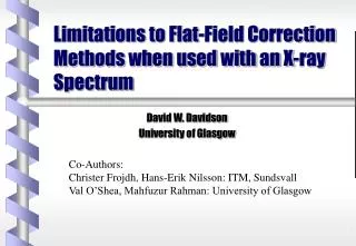
Limitations to Flat-Field Correction Methods when used with an X-ray Spectrum. David W. Davidson University of Glasgow. Co-Authors: Christer Frojdh, Hans-Erik Nilsson: ITM, Sundsvall Val O’Shea, Mahfuzur Rahman: University of Glasgow. Medipix Chip. Designed by M.Campbell (CERN)

E N D
Limitations to Flat-Field Correction Methods when used with an X-ray Spectrum David W. Davidson University of Glasgow Co-Authors: Christer Frojdh, Hans-Erik Nilsson: ITM, Sundsvall Val O’Shea, Mahfuzur Rahman: University of Glasgow
Medipix Chip • Designed by M.Campbell (CERN) • Single photon counting chip • Tunable threshold • 64 x 64 pixels • Silicon detector for X-rays David W. Davidson
Flat-Field Correction • Used to correct for inhomogeneity of response in X-ray imaging sensors • Numerous images are taken with the sensor exposed to a uniform field • The sensitivity of each pixel is determined by the average response and a gain map calculated • Further images can be corrected by dividing by this gain map • If the gain map is functioning correctly the variations remaining should be due to the statistical variation of the noise David W. Davidson
Flat-Field Correction Working Raw flood image taken at 70% exposure limit Image corrected using a gain map calculated from 50 such images David W. Davidson
Gain Map Variations • It has been seen that the gain map, taken for one source, will not correctly adjust for all sources using the same chip • Test effect of map on flood images • Set of flood images with non-monochromatic source to test for consistency • The variation of efficiency map with incident spectra is obtained David W. Davidson
Variation of gain map The incident spectra after various thicknesses of perspex shows beam hardening Change in gain map from no perspex to 40mm of perspex David W. Davidson
What effect does the wrong map have? • Each map was generated by 50 flood images • A flood image for each input spectra was then adjusted using each map • The distribution of counts was then examined • The standard deviation drops below Poisson value only for the correct map David W. Davidson
Explanation of gain map variation • Each photon absorbed in detector releases charge • This charge depends on photon energy and ionisation energy of detector material • Charge is drifted to electrodes • Loss in material included in charge collection efficiency (CCE) • Lack of uniformity across detector brings in use of gain correction factor per pixel • Any variation in effective thickness of detector medium will result in a variation of absorption efficiency dependent on incident energy spectrum • This gain correction factor will be dependent on the energy of the photon David W. Davidson
Mono-energetic X-rays • Signal per pixel for integrating and photon counting systems Sint = Ge * Fe * (1-exp(-ae * t)) * Qe Scount = Ge * Fe * (1-exp(-ae * t)) If Qe > Qth Ge = Gain constant Fe = No. of photons entering the pixel ae = Linear attenuation coefficient t = Effective detector thickness Qe = registered charge per photon (includes CCE) David W. Davidson
Spectrum of X-rays • Signal per pixel for integrating and photon counting detectors Sint = ∫ Ge * Fe * (1-exp(-ae * t)) * Qe de Scount = ∫ Ge * Fe * (1-exp(-ae * t)) de If Qe > Qth • However in practise the gain map is applied for all energies Sint = G* ∫ Fe * (1-exp(-ae * t)) * Qe de Scount = G* ∫ Fe * (1-exp(-ae * t)) de If Qe > Qth • This would only be correct if G were independent of energy David W. Davidson
Potential Solution • Possibility of calculating theoretical gain maps • Forming a database of gain maps • Reducing amounts of preparation work for any set of results • Interpolating between available gain maps David W. Davidson
Interpolating Maps • First simple test for different spectra • Result - • Improvement of factor 1.5 • Brings distribution to below Poisson (just like correct map) David W. Davidson
Summary • Correct flat-field adjustment is required so as to avoid phantom images (Artefacts) • Flat-field adjustment requires correct gain map • On each separate pixel the gain adjust is dependent on energy • Some calculation of theoretical gain maps is possible David W. Davidson
Final Solution • The use of monochromatic sources would remove this effect and allow correct adjustment of the image regardless of objects placed in the beam • The inclusion of an ADC on each pixel would allow the incident spectrum to be found and a correction for the relative intensity of each energy present would be possible or David W. Davidson