X-ray methods for nanoscience
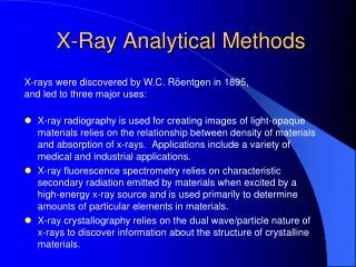
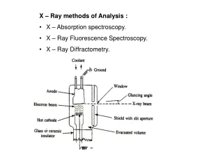
X-ray methods for nanoscience. Ritva Serimaa Department of Physics University of Helsinki. 20. 1. 2010. X-rays and matter. wavelength of the order of 0.1 nm. elastic scattering. x-ray beam. absorption. inelastic scattering. fluorescence. Why structural studies?.


X-ray methods for nanoscience
E N D
Presentation Transcript
X-ray methods for nanoscience Ritva Serimaa Department of Physics University of Helsinki 20. 1. 2010
X-rays and matter • wavelength of the order of 0.1 nm elastic scattering x-ray beam absorption inelastic scattering fluorescence
Why structural studies? • Understanding the relationship of structure, properties and function of a system • Monitoring the system during its formation for tuning the structure and properties • Dependence of the structure and properties on environmental conditions like temperature or pressure Course: Synchrotron radiation in materials research http://www.helsinki.fi/~serimaa/index-xraypk.html
How to produce x-rays? Large scale facilities ESRF First x-ray free electron lasers: Flash, LCLS http://www-ssrl.slac.stanford.edu/lcls/index.html The European XFEL is constructed in Hamburg http://xfel.eu/ • Synchrotron http://www.lightsources.org/cms/?pid=1001328 • European facilities: ESRF, MaxLab, Petra III, Soleil, …
Example of new synchrotrons: Petra III Hamburg • Ring was built for particle physics • Diameter about 3 km • German synchrotron • EMBL beam lines • 2015 Max IV Lund, Sweden
XFEL • Tiny samples • Coherent diffraction and imaging • Chemical reactions http://www.xfel.eu/research/examples/nanoworld/
Free electron laser (FEL) • FELs are usually based on the combination of a linear accelerator followed by a high-precision insertion device. • The accelerated electrons in the insertion device bunch together more tightly than usual. • Over the length of the insertion device, the electrons in the microbunches begin to oscillate in step (coherently). http://www.lightsources.org/cms/?pid=1001328
FEL http://en.wikipedia.org/wiki/Free_electron_laser
X-ray lithography (XRL) with table top and ordinary synchrotrons and lasers patterned films achieved in GGe by XRL structures with resolutions of the order of 100 nm • G Brusatin et al. Design of hybrid sol–gel films for direct x-ray and electron beam nanopatterning.Nanotechnology 19 (2008) 175306 • D Minkov et al. Targets emitting transition radiation for performing X-ray lithography by the tabletop synchrotron MIRRORCLE-20SX. Nucl Instr and Meth in Phys Res A: Accelerators… Vol 590, Iss 1-3, 2008, 110-113 • M.C. Marconia and P.W. Wachulak. Extreme ultraviolet lithography with table top lasers. Progress in Quantum Electronics Vol 34, Iss 4, 2010, 173-190
XFEL experimental stations 2014 • FXE femtosecond xray experiments: diffraction … • GED high energy density matter experiments, diffraction, inelastic scattering, spectroscopy • SPB single particles clusters biomolecules, coherent diffraction, resolution < 1 nm • MID materials imaging and dynamics, coherent diffraction, resolution around 10 nm • SQS small quantum systems, high resolution spectroscopy • SCS spectroscopy and coherent scattering, coherent imaging, photon correlation spectroscopy http://www.xfel.eu/research/experiment_stations/scs/
FLASH, small version of the European XFEL at DESY since 2005 • FLASH is 260 m long • soft X-rays down to a wavelength of 6 nm • A coherent diffraction pattern http://hasylab.desy.de/facilities/flash/research/a_perfect_image_from_a_single_fel_shot/index_eng.html
gold particles (diameter 10 nm) on a Si3N4 membrane The diffraction pattern was used to reconstruct the gold particle using the hybrid input-output (HIO) method together with the so-called shrink-wrap algorithm. Image with 5 nm spatial resolution. Coherent x-ray imaging (CXDI) SEM diffractionpatternreconstruction C. G. Schroer et al. Coherent X-Ray Diffraction Imaging with Nanofocused Illumination. PRL 101, 090801 (2008) (at ESRF ID 13) J. R. Fienup, Appl. Opt. 21, 2758 (1982). S. Marchesini et al., Phys. Rev. B 68, 140101(R) (2003).
X-rays are absorbed into the material or scattered. Attenuation is described by mass attenuation constant μ/ρ [cm2/g], where ρ is the density. I = I0 exp(-(μ/ρ) ρt), where t is the thickness. I0 I X-ray t Absorption needs to be taken into account and gives information on the sample
In X-ray tomography a series of radiographs are recorded for different angular positions of the sample which rotates around an axis perpendicular to the beam. Laboratory setups: cone beam, polychromatic radiation Synchrotron: parallel beam and monochromatic radiation X-ray microtomography The number of radiographs is the order of 1000 and the data is several Gigabytes. X-raysource http://laskin.mis.hiroshimau.ac.jp/Kougi/08a/PIP/ sample detector
X-ray microtomography setup at Department of Physics, Helsinki University • Phoenix nanotom 180 NF • Tungsten x-ray tube • Hamamatsu flat panel detector • One experiment • 1,440 projections • The measurement time for a single image 750 ms
Absorption as a function of energy • An x-ray photon is absorbed by the atom and the excess energy is transferred to an electron, which may be expelled from the atom, leaving the atom ionized X-ray http://physics.nist.gov/PhysRefData/XrayMassCoef/ElemTab/z28.html
X-ray absorption spectroscopy XAS • If x-ray energy is suitable, a photoelectron will be ejected. • X-ray absorption fine structure: The outgoing electron scatters from nearest atoms. This causes oscillations in the linear absorption coefficient. • Extended x-ray absorption fine structure EXAFS • X-ray absorption near edge structure XANES photoelectron X-ray XAS tutorials http://xafs.org/
XANES gives information on the electronic state of the absorbing atom and the local structure surrounding it. Oxidation state may affect the edge position. Shift of the edge <10 eV XANES X-ray absorption near edge structure Normalized absorption XANES EXAFS Data base for XANES spectra by Farrel Lyttle (http://www.esrf.fr/computing/scientific/dabax)
Studies on the averageenvironment of a selectedtype of atombyits absorption coefficient. EXAFSgivesinformation of distances and numbers of nearestneigbours of the chosenatomtype. EXAFS Extended x-ray absorption fine structure
Fluoresence analysis Elemental analysis Sample is irradiated by x-rays The emitted fluorescence radiation is detected. The elements are regognized on the basis of the energies of the x-ray fluorescence emittion lines. Example: J. Szlachetko et al. Application of the high-resolution grazing-emission x-ray fluorescence method for impurities control in semiconductor nanotechnology. J Appl Phys 105, 086101, 2009 http://en.wikipedia.org/wiki/X-ray_fluorescence
X-ray microcopy and XANES at ESRF 2-7 keV Spot size 0.3 – 1 micrometer http://www.esrf.eu/UsersAndScience/Experiments/Imaging/ID21/ http://www-cxro.lbl.gov/BL612/index.php?content=research.html
Micro-XRF image (1.5 × 0.2 mm) Aquatic plants Salvinia rotundifolia were exposed to Cr(VI). Micro-Xanes showed that Cr accumulated in the rootlet had been reduced to less toxic Cr(III). Detection limits from 1 to 10 μg/g for μ-XRF; from 100 to 1000 μg/g for μ-XAFS. The spatial resolution from 0.1 to 1 μm for X-rays of 2–30 keV μ-XRF and μ-XAS Hunter et al. Phys. IV Fr. 1997, 7, C2-767-C2-771 R. Ortega. Chemical elements distribution in cells. Nucl. Instr. Meth. in Phys. Res. B 231(1-4), 2005, 218-223
X-ray spectromicroscopy X-ray microscope on beamline X1-A1 at the National Synchrotron Light Source, Brookhaven National Laboratory JA Brandes et al. Carbon K-edge XANES spectromicroscopy of natural graphite. Carbon Vol 46, Iss 11, Sep 2008,1424-1434 S. C. Ray et al. Critical Reviews in Solid State and Materials Sciences, 31:91–110, 2006
X-ray imaging of biological systems • Imaging based on soft x-ray or electron microscopy • Radiation damage • Resolution < 100 nm • Samples • Frozen samples • Dehydrated specimens at room temperature. • Example: Scanning transmission X-ray microscopy and XANES at Carbon K absorption edge on Wood with resolution of 100 nm. XANES result: Polysaccharides are susceptible to soft X-ray irradiation induced chemical transformations GD Cody et al. Soft X-ray induced chemical modification of polysaccharides in vascular plant cell walls. J El. Spect and Rel. Phen. 170(1-3), March 2009, 57-64
X-ray scattering methods for structural studies Cullity and Stock: Elements of x-ray diffraction J Als-Nielsen, D McMorrow: Elements of modern x-ray physics Feigin, Svergun: Structure analysis by small-angle X-ray and neutron scattering. http://www.embl-hamburg.de/ExternalInfo/Research/Sax/reprints/feigin_svergun_1987.pdf
q = k2-k1 q X-ray scattering Scattering vector q, length q = 4π/λsinθ where λ is the wavelength and 2θ the scattering angle • SAXS and WAXS • WAXS q X-rays 2θ monochromator sample detector Symmetrical transmission Symmetricalreflection X-rays k1 k2
ESRF ID2 http://www.esrf.eu/UsersAndScience/Experiments/SoftMatter/ID02/BeamlineLayout
X-ray scattering WAXS, SAXS, USAXS, XRD … • Wavelength of the order of 0.1 nm • X-rays scatter from electrons. • Scattering amplitude A(q) is proportional to Fourier transform of the electron density (x): A(q) = (y) exp(i q·y) d3y Here qis the scattering vector. • Intensity I(q) = A*A may be presented as a Fourier transform of the autocorrelation function C(z) of the electron density: • I(q) = C(z) exp(-i q·z) d3z • Here C(z)= (z+y) (y) d3y
q k1 k2 d x Bragg law 2d sin θ = λ • Scattering vector q = k2 - k1 is perpendicular to the lattice planes. The lenght of the scattering vector |q| = 4π/λ sinθ • Bragg law in terms of q: d = 2π/q Path difference 2x x/d = sin θ 2x = 2d sin θ = λ
Crystallography of macromolecules • Cellulose Ia The oriented fibrous samples prepared by aligning cellulose microcrystals from the cell wall of the freshwater alga Glaucocystis nostochinearum. Nishiyama Y, Sugiyama J, Chanzy H, Langan P. Crystal structure and hydrogenbondingsystem in cellulose Ia fromsynchrotronX-ray and neutronfiberdiffraction. J Am ChemSoc 125(47), 14300-14306, 2003
Isotropic crystalline powder sample • Diffraction pattern consists of rings • Example. Silver behenate • Crystal structure from the positions of the peaks • Crystallite size from the FWHM’s of the peaks http://chemistry.library.wisc.edu/subject-guides/x-ray-crystallography.html
Anisotropic crystalline sample Diffraction pattern may consists of ”spots” Crystal structure Crystallite size Preferred orientation of crystallites from the azimuthal intensity of one reflection Example: paper - cellulose and filler q
Semicrystalline materials: Crystallinity from WAXS intensity • Crystallinity index = Intensity of crystalline model -------------------------------------- Experimental intensity Solid bamboo sample • Crystalline intensity from model • Amorphous pattern measured from a lignin sample. Reflection mode Transmission mode
Crystallite size from the width of the reflections • Scherrer formula L = K λ/(B(2θ) cosθ), where K is a constant, B(2θ) is the the full width at half maximum of the reflection, 2θ is the scattering angle and λ the wavelength. • Instrumental broadening of the reflection should be considered. • Extraction of a diffraction peak from the intensity curve. FWHM
Crystallite size vs grain size • Grain size from electron microscopy, microtomography • Crystallite size using x-ray diffraction • Grains can contain several crystallites
Structure factor and radial distribution function Carbon nanotube Experiment at high energy x-rays Koloczek J, Hawelek L, Burian A, et al. Modelling studies of carbon nanotubes - Comparison of simulations and X-ray diffraction data. Journal of Alloys and Compounds Vol 401 Iss1-2, 46-50 SEP 29 2005
Fast experiments with pink synchrotron beam Kong Q., Wulff M., Lee J.H., Bratos S., Ihee H., Photochemical reaction pathways of carbon tetrabromide in solution probed by picosecond X-ray diffraction. J Am Chem Soc 129, 13584-13591 (2007)
Small-angle x-ray scattering and diffraction • Crystal structures in length scales 1-100 nm • Macromolecules in solution: shape and size • Fractal structures: fractal dimension • Two-phase systems with sharp interfaces: spesific surface Feigin LA, Svergun DI. Structure analysis by small-angle X-ray and neutron scattering. http://www.embl-hamburg.de/ExternalInfo/Research/Sax/reprints/feigin_svergun_1987.pdf Glatter O, Kratky O (1982). Small Angle X-ray Scattering. http://physchem.kfunigraz.ac.at/sm/
Small-angle diffraction: nanoporous silica Two-dimensional Hexagonal structure d-2 = 4/3 (h2 + hk + k2)/a2 Values of h and k for first peaks: 01, 10 1 1 0 2 DirkMter et al. Surfactant Self-Assembly in Cylindrical Silica Nanopores. J. Phys. Chem. Lett., 2010, 1 (9), pp 1442–1446
Mesoporous silica F Kleitz, S Hei Choi, R Ryoo. Cubic Ia3d largemesoporoussilica: synthesis and replication to platinumnanowires, carbonnanorods and carbonnanotubes. Chem. Commun., 2003, 2136-2137
C16E7–D2O system BL-15A instrument at the Photon Factory in KEK, Japan Block co-polymers and surfactants M Imaia et al. Kinetic pathway of lamellar \ gyroid transition: Pretransition and transient states. J. Chem. Phys., Vol. 115, No. 22, Dec 2001, 10525-10531
Electron density Shape of objects in dilute solution using SAXS Amplitude of a sphere with electron density ρand radius a: F(q) = 4/3 π a3 ρ 3 (sin x –x cos x)/x3, where x = qa. Electron density ρ a r Blue: intensity of spheres, a = 30 Å. Green: Guinier law I ~ exp(-1/3 Rg2 q2) http://www.embl-hamburg.de/research/unit/svergun/index.html http://kur.web.psi.ch/sans1/SANSSoft/sasfit.html
Guinier law. At small q the intensity can be approxi-mated with a Gaussian: I(q) ≈ I(0) exp(-(1/3)(qRg)2 ) The radius of gyration Rg = ∫ρ(r)r2 dV / ∫ρ(r)dV Figure: Rg = 25.1 Å V = 45475 Å3≈ (36)3 Å3 Sphere R = 32 Å SAXS of hydrophobin protein in a dilute solution
Crystalline structure Hydrophobin protein and model based on a fit to measured SAXS intensity Hakanpaa JM, Szilvay GR, Kaljunen H, Maksimainen M, Linder M, Rouvinen J. Two crystal structures of Trichoderma reesei hydrophobin HFBI -The structure of a protein amphiphile with and without detergent interaction. Protein Sci. V15, 2129-2140, 2006 http://www.embl-hamburg.de/ExternalInfo/ Research/Sax/software.html
Power law behaviour of SAXS intensity from solutions • IN(q) ≈ 4π (ρ- ρ0)2 S/q4at large q, where S is the total area of particles and ρ- ρ0electron density difference • Sheets I(q) ≈ const /q2 • Long thin rods I(q) ≈ const /q1 I ≈ 1/q4 e.g. Teixeira. J.Appl. Cryst. 21 1988, 781-785 and SAXS text books
Flexible polymers with Gaussian statistics • Intensity is proportional to F(q) = 2(exp(-u) + u - 1)/u2 where u = <Rg2>q2 and <Rg2> is the average radius of gyration squared. • <Rg2> = (Lb)/6, where L is the contour length and b is the statistical segment length.
Dense systems: fractal aggregates • The SAXS intensity follow a power law • I ≈ 1/qa. • This can be interpreted as arising from fractal structures, if the characteristic length scale R of a fractal satisfies the condition Rq >>1. • For surface fractals the power law exponent a is between 3 and 4. It is related to surface fractal dimension Ds as a = 6 - Ds. • The Porod law, a = 4, is valid for the scattering of a compact particle with a smooth surface (Ds = 2, Dm = 3) • A power law with a < 3 is caused by a mass fractal for which a = Dm = Ds < 3. • Continuous charge density transitions can cause a to be larger than 4.
μ-SAXS and microfluidics T. Pfohl et al.Trends in microfluidics with complex fluids, Chem. Phys. Chem.4 (2003), pp. 1273–1274. Piggee C. Sometimes less is more: microfluidics extends the capabilities of SAXS. Analytical Chemistry 80(11), 3948-3948, 2008
GIXD Grazing incidence x-ray diffraction Troika beam line of ESRF Side view PSD αf αi Film surface Top view w2 w1 Soller slits Surface structures PSD λ = 2π/k, qxy = 2ksinθ, qz ≈ k sinαf