Download
1 / 17
170 likes | 294 Vues
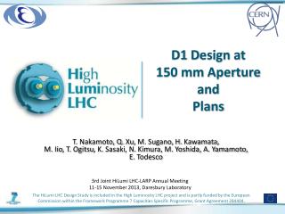
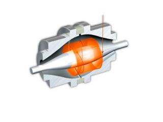
Cross-section of the 150 mm aperture case. Paolo Ferracin. HiLumi WP3 Video-meeting 26 July, 2012. Outline. Design concept Conductor properties Magnet parameters Stress analysis Some additional considerations. From HQ to MQXF Magnetic design concept. HQ. MQXF.

E N D
Cross-section of the 150 mm aperture case Paolo Ferracin HiLumi WP3 Video-meeting 26 July, 2012
Outline Paolo Ferracin • Design concept • Conductor properties • Magnet parameters • Stress analysis • Some additional considerations
From HQ to MQXFMagnetic design concept HQ MQXF Paolo Ferracin • Aperture: from 120 mm to 150 mm • Cable width: from 15 mm to 18 mm wide cable • 2 layers with similar angles and 4 blocks • All harmonics below 1 unit at 2/3 of Rinand 80% of Iss • Similar iron geometry, but with OD from 520 mm to 558 mm
From HQ to MQXFMechanical design concept HQ MQXF Paolo Ferracin • Same support structure concept as HQ • Same shell thickness, but OD from 570 mm to 608 mm • Cooling holes and busbar slots added • 10 mm thick LHe vessel included within 630 mm OD
Conductor properties Paolo Ferracin • From 0.80 to 0.85 mm strand • Cu/Sc ratio: 1.13 (53% Cu) • Assumption on Jc • 2500 A/mm2 at 12 T • 1400 A/mm2 at 15 T • Resulting Jc for computations with self field correction • 2650A/mm2 at 12 T • 1450A/mm2 at 15 T • Values consistent with D. Dietderich and H. Felice presentation and with FRESCA2 PIT strand data
Cable and coil parameters HQ MQXF Paolo Ferracin • From HQ to MQXF • Wider cable • Increased insulation • 43% more conductor
Magnet parameters at 1.9 K HQ MQXF Paolo Ferracin
Magnet parameters at 1.9 K * Analytical peak stress on mid-plane ** FEM peak stress (1.9 K / Gnom) Paolo Ferracin • Comparison with expectations • see “Proposal for aperture”, E. Todesco, 02/07/2012
Fringe field MQXF HQ Paolo Ferracin • At 5 mm from the cryostat, fringe field ranging from 3 mTfor HQ to 8 mTfor MQXF
Stress analysis • Lorentz stress on mid-plane • IL: -101 MPa • OL: -121 MPa • Bladder press. / interf. • 17MPa / 0.160 mm • Max shell stress: 150MPa • Lorentz stress on mid-plane • IL: -113 MPa • OL: -122 MPa • Bladder press. / interf. • 27MPa / 0.430 mm • Max shell stress: 230MPa HQ MQXF Paolo Ferracin
Stress analysisCoil peak stress HQ @ 1.9 K -137 MPa MQXF @ 1.9 K -150 MPa HQ @ Gnom -119 MPa MQXF @ Gnom -129 MPa Paolo Ferracin
Some additional considerations on MQXF (I) • Coil optimization • Alternative solution with 53 turns • +2 in outer layer • Sharp wedge and 1 unit of b14 • But…. • 1% of additional margin wrt. Iss • 2% reduction of JO • Reduction of few (4-5) MPa of Lorentz stress on mid-plane (IL) • But smaller effect coil peak stress during operation (work in progress) 51 turns 53 turns Paolo Ferracin
Some additional considerations on MQXF (II) Paolo Ferracin • Cooling holes • 80 mm diameter • Could be increased to 90 mm, depending on axial support system • Busbar • 20 x 50 mm slot • Axial support • 32 mm axial rods • Some space for end-plate and pad-bolts • High stress but probably still fine • Alternative: end-plate welded to vessel
Some additional considerations on MQXF (III) • LHevessel • 10 mm thick cylinder • OD: 630 mm • 1 mm gap between vessel and Al shell (nominal dimension) • About 0.500 mm clearance after pre-loading, cool-down, and excitation • Still to be verified the welding procedure • Other modifications/simplifications • Round collars? • No masters? MQXF Paolo Ferracin
Conclusions Paolo Ferracin • Preliminary analysis of MQXF design based on HQ-concept • 150 mm aperture, wider cable, OD 630 mm • MQXF can generate a gradient of 140 T/m with 20% margin at 1.9 K • 65% higher stored energy than HQ, but similar stored energy density and lower J0 • About 10 MPa higher coil peak stress (from 140 to 150 MPa) • Support structure within stress limits • Further optimization of coil and structure in progress
Appendix Paolo Ferracin
Stress analysisComparison at 80% of Iss Paolo Ferracin • From HQ to MQXF_15mm • IL Lorentz stress: +13% • Peak stress: +15 MPa • From MQXF_15mm to 17mm • Reduction of 10 MPa in peak stress