Advanced Techniques for High-Resolution Imaging in Nanowires Lab Reports
Explore detailed procedures and calculations for achieving optimal resolution in nanowire imaging using electron microscopy techniques. Learn about minimizing vibrations, optimizing convergence angles, and improving contrast for precise visualization.

Advanced Techniques for High-Resolution Imaging in Nanowires Lab Reports
E N D
Presentation Transcript
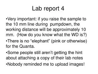
Lab report 4 Very important: if you raise the sample to the 10 mm line during pumpdown, the working distance will be approximately 10 mm. (How do you know what the WD is?) There is no “elephant” (pink or otherwise) for the Quanta. Some people still aren’t getting the hint about attaching a copy of their lab notes Nobody reminded me to upload images!
High resolution imaging • Why? • To see really tiny stuff! • Soot particles (Combustion research) • Gold nanoparticles and nanorods (Jennifer Shumaker-Parry) • To get really sharp images of “fairly small” stuff • Gold nanoparticles and nanorods (Marc Porter…) • Same considerations should apply to e-beam lithography
High resolution imaging • How? • FEG Why? • dp2 = 4ip/( π2 * β * αp2) • To see small stuff, you need a small spot. • Small spot requires • Low probe current (small “spot size”) • High brightness • Large aperture angle • αp = dA/2*WD • Short working distance • Large aperture? We’re still arguing over that one, but nobody believes it!
Optimum convergence angle • The previous equation can be differentiated and the derivative set equal to zero • Result is quadratic in α4
Optimum convergence angle • If chromatic aberrations can be neglected: • αopt = [2/3Cs2)(8ip/βπ2 + 0.72 λ2)]1/8 • At 10 kV, λ = 0.01 nm, 100 pA, and β = 108 A/cm2sr Cs = 2 mm, then αopt = 6.4*10-3 rad • αp = dA/2*WD • If dA = 30 microns: WD = 2.4 mm • At 1 kv λ increases by a factor of 10 • αp increases to 9 mrad • WD decreases to 1.7 mm • Much shorter for W-filament! • Note that αopt was 4 mrad for W-filament (Cs = 10 mm), 20 kV in Fig 2.22.
High resolution imaging • What’s the point of all this math for high resolution imaging? • Short WD is important! • ETD is out of the game • Other options • TLD • vCD • Helix • Immersion mode increases resolution about another order of magnitude
High resolution imaging • Minimize emi (Ian’s lecture of last Friday!) • Minimize floor vibrations • Each lab in INSCC is on an individually poured slab of concrete • Minimize acoustic vibrations (audio noise) • Minimize temperature fluctuations • Try “Mains lock” • Replace carbon tape with silver or carbon paste • Use single sample mount
When do we run out of resolution? As a result when the feature size is close to the SE escape range l the object is not resolved. This occurs at ~ 5-10nm for low Z materials SE1 have a range of a few nm and create the ‘edge bright line’ effect DCJ - High Resolution 14
In other samples... When an object gets small enough to be comparable with the SE1 generation volume then it becomes bright all over and the defining edges disappear. For low Z, low density materials this can happen at a scale of 5-10nm edge brightness no edges Carbon nanotubes 5nm and 10nm wide DCJ - High Resolution 15
SE image of Single Wall NanoTube DCJ - High Resolution 16
..but how wide is this nanotube? If these are the edges then width = 1.5nm If these are the edges then width = 5.8nm • The image does not have defined edges - its width is indeterminate and equal to lcarbon ? lC =5.5nm DCJ - High Resolution 17
Bypassing the SE1 limit Metals have lower than carbon, and a higher SE yield A thin metal film on a low Z, low density sample localizes all SE production within itself. The resolution now is a function of the film thickness only Works even with very thin metal films (a few atoms thick) We can exploit this effect to give interpretable contrast beyond the theoretical limit High SE yield Low SE yield width ~ film thickness even when < DCJ - High Resolution 18
Mass thickness contrast The SE1 yield varies with the thickness of the metal SE1 yield reaches the bulk value at a film thickness equal to about 3 The conformation of the film to surface topography provides contrast bulk value S E Y i e l d mass thickness variation 1nm 2nm 3nm Film thickness DCJ - High Resolution 19
Metal builds contrast The SE localization in the film provides edge definition The mass thickness effect gives extra contrast enhancement The feature is now ‘resolved’ since its size and shape are visible 5nm low Z object 2nm metal film SE Beam position SE profile with metal film SE profile without metal DCJ - High Resolution 20
Cr coatings Cr films are smooth and without structure even as thin as 1nm The mass thickness contrast resolves edges and make the detail visible down to a nanometer scale The high SE yield of the Cr improves the S/N ratio However these coatings are not stable - so use Cr coated samples immediately after they have been made • T4 Phage • coated with Cr T4 Phage + Cr • courtesy of Martin Müller • and Rene Herrmann, ETH Zürich DCJ - High Resolution 21
Coating Summary Coatings are an essential part of the technique of high resolution SEM because they generate interpretable contrast, improve resolution, and enhance the S/N ratio Thin coatings are better than thick coatings - do not make your sample a piece of jewelry Below 100kx particulate coatings are useful because of their higher SE yields and better S/N ratios Above 100kx can use chromium or titanium or particulate coatings of W,Pt or Ir Carbon is a contaminant not a coating DCJ - High Resolution 22
Helix Detector • Looks just like the LowVac detector • Mounts just like the LowVac detector • Costs $28.5k • “You break it, you bought it.” • Runs in Immersion Mode, like the TLD • Gives super images in LowVac • Aperture is 62 microns
Helix detector settings • 1- why and when should Helix detector voltage be changed? • Helix detector voltage should be optimized after every parameter change. This just means, from the previous Helix sweet spot, needing to bump it up or down a 1% or 2% after changing a parameter like water, FWD, beam current, kV, dwell. • I believe Helix needs to be running at full current, just prior to arcing, at all times. A typical Helix session may run like this; 78.5% voltage = arcing, 77.5% voltage = no arcing and good signal contrast, 76.5% voltage = no arcing and poor contrast. I don’t expect you to see identical numbers as these but I’d expect you to experience a similar “narrow window” of good zone. • For me, Helix sweet spots are 1%-1.5% off saturation, 3.2-mm FWD, 4kV- 7kV, as much as 30% less water than what was needed for LVD. • Reducing Spot size just means increasing dwell times but I typically work between spots 2.0 and 3.0
vCD Detector • Backscatter detector • Mounts on pole piece • Has small aperture; will work in LowVac • Works with beam deceleration • Works in immersion mode