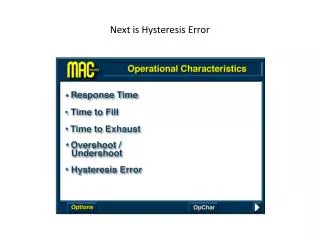
Understanding Hysteresis Error and Response Time in Piezo Systems
This presentation explores the hysteresis error in Piezo systems, focusing on operation via a 10V command. Watch as we demonstrate the system's quick response and exhaust times when applying commands. We identify parts critical to performance, such as small orifices that affect response times and susceptibility to contamination. Key comparisons between MAC and SMC systems illustrate differences in response and fill times. You'll see how contamination can lead to coil burnout, emphasizing the importance of design and maintenance.

Understanding Hysteresis Error and Response Time in Piezo Systems
E N D
Presentation Transcript
Explain the operation Click Options then MAC
Applying a 10volt command – note fast response time and quick fill on 1 cu.in. volume
Applying 0 volt command note fast response and quick exhaust time on 1 cu. In. volume CLICK OPTIONS / SURF / SMC / START
This is the Piezo Type – a Constant Bleed System CLICK HERE TO MUTE SOUND
LET’S IDENTIFY THE PARTS CLICK
TALK ABOUT THE PARTS BUT POINT OUT THE SMALL ORIFICES AS THEY RELATE TO RESPONSE TIME AND CONTAMINATION CLICK
Put the cursor here to activated yellow highlighted area and click on it
Again, small orifice results in longer response time and susceptible to contamination. CLICK
AS CONTAMINENTS BUILD UP THROUGH SMALL ORIFICE YOU CAN HAVE COIL BURNOUT. CLICK
BURNOUT CLICK
NOW THAT THE 10 VOLT IS COMMANDED LET’S FOLLOW THE SEQUENCE OF OPERATION CLICK
Flapper deflects down reducing orifice Bleed creating back pressure on piston/ diaphragm
Piston/Diaphragm moves down, shifts poppet, air begins to flow
FLAPPER DEFLECTS UP, OPEN ORIFICE RELIEVES BACK PRESSURE ON PISTON/DIAPHRAGM
LET’S COMARE WITH MAC CLICK
MAC VS SMC ENERGIZED TRACES SHOWING RESPONSE AND FILL TIME - LETS COMPARE
THE COMPARISON TRACES SHOW ENERGIZE RESPONSE TIMES OF Mac 6ms to SMC 200ms and fill time of 100ms vs 1000ms
LET’S COMPARE BOTH ENERGIZED AND DEENERGIZED TOGETHER – MAC HAS A BETTER RESPONSE TIME CLICK ON RESET
LET’S EXAMINE THE SMC DESIGN CLICK ON FLAPPER HIGHLIGHTED AREA
NOTE THE CONSTANT BLEED CLICK
THE ELECTRONICS IS BEING EXPOSED TO AIR PRESSURE, CONTAMINATION, AND MOISTURE CAUSING BOARD TO BURN OUT WAIT FOR THE NEXT SCREEN TO APPEAR
BURNOUT CLICK
NOTE THE SMALL ORIFICE AREA THAT IS SUBJECT TO CONTAMINATION BUILD UP CLICK
WE WILL NOW PROCEED TO A 2 VALVE DESIGN CLICK OPTIONS/ PROPORTION AIR / START