Magnetic hysteresis
Magnetic hysteresis. Group V. sub: ELEMENTS OF ELECTRICAL ENGINEERING Code:2110005 Part of active learning assignment Ankit Makwana 13BEEEN085 Dhaval Darji 13BEEEG122 Parth Tank 13BEEEG065 Biren Panchal 13BEEEG099. Magnetization or B-H Curve.

Magnetic hysteresis
E N D
Presentation Transcript
Group V • sub: ELEMENTS OF ELECTRICAL ENGINEERING • Code:2110005 • Part of active learning assignment • Ankit Makwana 13BEEEN085 • Dhaval Darji 13BEEEG122 • Parth Tank 13BEEEG065 • Biren Panchal 13BEEEG099
The set of magnetization curves, M above represents an example of the relationship between B and H for soft-iron and steel cores. • Every type of core material will have its own set of magnetic hysteresis curves. • The flux density increases in proportion to the field strength until it reaches a certain value were it can not increase any more.
This is because there is a limit to the amount of flux density that can be generated by the core as all the domains in the iron are perfectly aligned. • Any further increase will have no effect on the value of M, and the point on the graph where the flux density reaches its limit is called Magnetic Saturationalso known as Saturation of the Core
The Magnetic Hysteresis loop above, shows the behavior of a ferromagnetic core graphically . • The relationship between B and H is non-linear. An unmagnetised core both B and H will be at zero, point 0 on the magnetization curve. • If the magnetization current, i is increased in a positive direction to some value the magnetic field strength H increases linearly with i and the flux density B will also increase as shown by the curve from point 0 to point a towards saturation.
Now if the magnetizing current in the coil is reduced to zero the magnetic field around the core reduces to zero but the magnetic flux does not reach zero due to the residual magnetism present within the core and this is shown on the curve from point a to point b. • To reduce the flux density at point b to zero we need to reverse the current flowing through the coil. The magnetizing force which must be applied to null the residual flux density is called a "Coercive Force". This coercive force reverses the magnetic field re-arranging the molecular magnets until the core becomes unmagnetised at point c.
. An increase in the reverse current causes the core to be magnetized in the opposite direction and increasing this magnetization current will cause the core to reach saturation but in the opposite direction, point d on the cure which is symmetrical to point b. • If the magnetizing current is reduced again to zero the residual magnetism present in the core will be equal to the previous value but in reverse at point e.
Again reversing the magnetizing current flowing through the coil this time into a positive direction will cause the magnetic flux to reach zero, point f on the curve and as before increasing the magnetization current further in a positive direction will cause the core to reach saturation at point a. • Then the B-H curve follows the path of a-b-c-d-e-f-a as the magnetizing current flowing through the coil alternates between a positive and negative value such as the cycle of an AC voltage. This path is called a Magnetic Hysteresis Loop.
A good permanent magnet should produce a high magnetic field with a low mass, and should be stable against the influences which would demagnetize it. The desirable properties of such magnets are typically stated in terms of the Remanence and Coercivity of the magnet materials. • When a Ferromagnetic material is magnetized in one direction, it will not relax back to zero magnetization when the imposed magnetizing field is removed. The amount of magnetization it retains at zero driving field is called its Remanence.
It must be driven back to zero by a field in the opposite direction; the amount of reverse driving field required to demagnetize it is called its coercivity. • The table below contains some data about materials used as permanent magnets. Both the coercivity and remanence are quoted in Tesla, the basic unit for Magnetic field B. The hysteresis loop above is plotted in the form of Magnetization M as a function of driving magnetic Field strength H.
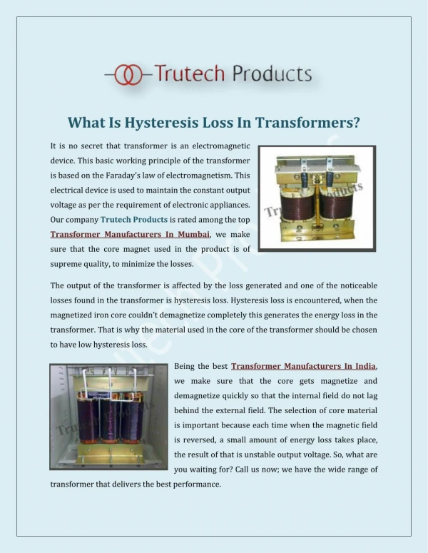
Hysteresis Loss • Due to presence of magnetic hysteresis a fraction of applied power will be lost in the form of heat. • The portion of power lost corresponds to the difference between the energy stored and energy returned back by the magnetic core .This is called Hysteresis loss.
If the magnetic field applied to a magnetic material is increased and then decreased back to its original value, the magnetic field inside the material does not return to its original value. • The internal field 'lags' behind the external field. This behaviour results in a loss of energy, called the hysteresis loss, when a sample is repeatedly magnetized and demagnetized. • . The materials used in transformer cores and electromagnets are chosen to have a low hysteresis loss.
Factor Affecting The Hysteresis Loss • Frequency of Magnetization. • Volume of the Material. • Area enclosed by the Hysteresis Loop. • Area of the Hysteresis Loss : The Hysteresis Loss is directly Proportional to the area under the Hysteresis Loop . For the loss materials the Hysteresis Loop is narrow.
The area and the shape of the magnetic material are the important parameters which decide the suitability of a material for a particular application. • In theHysteresis Loop of Soft Ferromagnetic material all the values such as residual magnetism and coercive force are moderate . Hence this material is used for making the electromagnets.
In theHysteresis Loop of Hard Ferromagnetic material all the values such as residual magnetism and coercive force are Large . Hence this material is used for making the permanent magnet.
Application of Magnetic hysteresis • There are a great variety of applications of the hysteresis in Ferro magnets. • Many of these make use of their ability to retain a memory, for example Magnetic Tape, Hard Disk, and Credit Card. • Hard magnets (high coactivity) like iron are desirable so the memory is not easily erased.
Soft magnets (low coercivity) are used as cores in electromagnets. • The low coercively reduces that energy loss associated with hysteresis.
Other Application of Magnetic Hysteresis • Magnetic hysteresis brakes use permanent magnets surrounding a hysteresis disc to provide a constant torque, without external power. • By varying the displacement of the magnetic hysteresis disk, this torque can be quickly adjusted by a machine operator.
The magnetic brakes are ideally suited to control winding applications in the wire, cable and converting industries and anywhere a constant torque is required.
Magnetic tape Quarter-Inch Cartridges
The reverse side of a typical credit card 1-Magnetic Stripe 2-Signature Strip 3-Card Security Code