Download
1 / 33
330 likes | 358 Vues
Learn about the FRC Control System 2015, including the Power Distribution Board, RoboRIO, Pneumatic Control Module, and more. Understand the different modules and their functions in the control system.

E N D
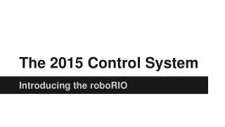
2015 FRC Control System 101010 = MOL = DUK
2014 Power Distribution Board (4) 40 amp Circuits (6) 20/30 amp Circuits 12 Volt (DAP Bridge) + 12 Volts 24 Volt (cRIO) -12 Volts 5 Volt (Camera) 40 amp Circuits (4) 20/30 amp Circuits (6)
2015 Power Distribution Panel (4) 20/30 amp Circuits (4) 40 amp Circuits CAN VRM Voltage Regulator Module PCM Pneumatic Control Module + 12 Volts RoboRIO -12 Volts 20/30 amp Circuits (4) 40 amp Circuits (4)
2014 NI 4-Slot cRIO Analog Module Solenoid Module (Optional) Serial Port Optional: Analog Module Digital Module Solenoid Module 24v DC Power Ethernet Port Digital Module
Digital Side Car – Analog Breakout PWM Outputs (10) (Motor Controllers and Servos) 37-pin Connector (cRIO Digital Module) 12v Power Input 12v Power Input Analog Inputs (8) Robot Signal Light Battery Voltage Jumper Relay Status LEDs I2C Header and Connector Digital Input/Output (14) Relay Output (8) 12-bit ADC with range of -10 to +10 Vdc (With 0 -5 Vdc input ADC counts = 0 to 1023) Connector (DB25) (cRIO Analog Module)
2015 NI RoboRIO Status LEDs USB Device USB Host Power: Green=OK Amber=Brownout Red=Fault Status: On=Booting Off=OK Blinking=Error Radio: NA Comm: Off=None Red Solid=No Code Red Blink=E-Stop Green Solid=OK Mode: Off= Disabled Green=Autonomous Amber=Teleop Red=Test RSL: Off=Robot Off On=Robot Disabled Blinking=Robot Enabled 12v Power SPI Ethernet CAN I2C RS-232 DIO (10) MXP PWM (10) Accelerometer CAN = Controller Area Network DIO = Digital Input / Output I2C = Inter-Integrated Circuit MXP = myRIO Expansion Port PWM = Pulse Width Modulation RS232 = Serial Port Standard RSL = Robot Signal Light SPI = Serial Peripheral Interface Dimensions: 5.7” x 5.6” x 1.3” Pin Spacing = 0.1” I/O Spacing = 0.3” RSL Relay (4) Analog IN (4) 12-bit ADC with 0-5v range
2015 RoboRIO MXP myRIO Expansion Port Shared: 10 - PWM Outputs (Disabled when Robot is Disabled) 16 - DIO 1 - I2C Port 1 - SPI Port 4 - Analog Inputs 2 - Analog Outputs 1 - RS-232 Port http://www.usfirst.org/roboticsprograms/frc/blog-myRIO-Expansion-Port- Whats-the-Deal.
2014 Pneumatics Solenoid Module & Breakout Spike Relay Digital Input 12/24v Power Input Relay Outputs (8) (Max current/channel = 0.75A) (Maximum Total = 21W)
2015 Pneumatics Control Module 12v Power Pressure Switch Input CAN Compressor Relay Output Solenoid (4) Solenoid (4)
2014 Power Converter 12v –to-5v
2015 Voltage Regulator Module 12v Power Radio Power Custom Circuits Camera Power Custom Circuits
Weidmuller LSF Connectors • For best results: • Wire should be 16AWG to 24AWG (consult rules to verify required gauges for power wiring) • Wire ends should be stripped approximately 5/16“ • To insert or remove the wire, press down on the corresponding "button" to open the terminal • After making the connection check to be sure that it is clean and secure: • Verify that there are no "whiskers" outside the connector that may cause a short circuit • Tug on the wire to verify that it is seated fully. If the wire comes out and is the correct gauge it • needs to be inserted further and/or stripped back further.
RoboRIO Networking mDNS Multicast Domain Name System (mDNS) is a system which allows for resolution of host names to IP addresses on small networks with no dedicated name server. (roboRIO-TEAM.local) The FRC Driver Station, LabVIEW, and the Eclipse plugins for C++ and Java are all programmed to discover your roboRIO using mDNS protocol. This means the roboRIO can be detected regardless of the interface or IP being used. USB When using the USB interface, no setup is required. The roboRIO driver will automatically configure the IP address of your computer and the roboRIO. Wireless The 2015 Bridge Configuration Utility will enable the DHCP (Dynamic Host Configuration Protocol) service on the DAP radio when in AP mode. The bridge is configured with a 10.TE.AM.1 IP address and will hand out DHCP addresses from 10.TE.AM.20 to 10.TE.AM.199. When the DAP radio is in bridge mode at competitions, the FMS will be the DHCP server.
2015 Driver Station PC: Battery CPU % Battery Voltage Chart Log Menu ViewMenu Messages Operation Operation Diagnostics Settings USB CAN Messages Charts Both
2015 Driver Station Operation Chart Diagnostics Messages + Chart Reboot Restart
2015 Driver Station Settings Messages USB Messages Test for Joystick Axes and Buttons 6 - Joysticks
DS Deleted Features eStop Robotics: CCI No Cypress I/O No Kinect No User Messages
PDP Data Charting 20 hz Capture Rate
PDP Charting 20 hz Capture Rate
Feature Changes • Zero-based input/output channel numbering • Class: +Additions, -Deletions, *Changes: (C++ and Java) +BuiltInAccelerometer -AnalogModule *AnalogAccelerometer +PowerDistributionPanel -DigitalModule *AnalogInput +AnalogOutput -DriverStationEnhancedIO *Compressor -DriverStationLCD *IterativeRobot (No SetPeriod) -Kinect • Analog-to-Digital Convertor cRIO: -10v to +10v 12-bit 0 - 1023 (at 5v) roboRIO: 0 to +5v 12-bit 0 - 4095 • Brownout Protection PWM outputs disabled when voltage drops below 6.50v (Restored at 7.50v) DIO power turned off when voltage drops below 6.25v (Restored at 6.60v) • Eclipse for C++ and Java Code Development • RoboRIO mDNS: roboRIO-team.local (roboRIO-525.local)
Robot Signal Light 2014 Signals 2015 Signals