SVX4 and PHENIX Integration: Sensor Testing Platform Development
60 likes | 82 Vues
This project involves creating a sensor testing platform for the proposed PHENIX sensor, utilizing SVX4 technology. The platform includes a 3cm x 6cm device with 80um x 1mm pads connected into strips, facilitating readout at edges and center. The 128-channel Si-strip readout chip developed by FNAL/LBNL supports pipelined digitization, 4-event LVL1-accept buffering, and multi-stage pedestal subtraction. The testboard, controlled by a LabView GUI, mimics the PHENIX DAQ and provides means to test SVX4 with a sensor. Testboard development status includes communication establishment, near-complete LabView GUI, and FPGA programming in progress. Despite upcoming team absences, compatibility testing with the pseudo-PHENIX DAQ is planned for August, with sensor testing targeted for September.

SVX4 and PHENIX Integration: Sensor Testing Platform Development
E N D
Presentation Transcript
SVX4 and PHENIX Vince Cianciolo (ORNL) Ken Read (ORNL/ UT) 9 June 2003
Proposed PHENIX sensor • 3cm x 6cm device • 80um x 1mm “pads” connected into 80um x 3cm strips • 750 strips per orientation per sensor • Readout at edges and center “x” readout “u” readout
128-channel Si-strip readout chip developed by FNAL/LBNL. Pipelined digitization and readout (42-deep pipeline for analog samples). 4-event LVL1-accept buffering. On-board zero-suppression available (or not). Multi-stage pedestal subtraction. Designed for AC-coupled device (Z. Li sensors DC-coupled). Two handles: Frequent storage-cap resets. Cool sensors to 0 degrees C to reduce leakage current. Certainly able to do first. May suffice, but may want to cool anyway. Integration time (~80 ns) much shorter than sensors have been tested at. Possibly worse S/N. FNAL indicated willingness to do wafer-testing. SVX4
New Testboard Clock FPGA Input FIFO Output FIFO Ribbon Cable CDF Hybrid Testboard Wire bonding CDF Hybrid SVX4 SVX4 SVX4 SVX4 SVX4 Testboard PC LabView GUI USB Connection The point of the testboard we are developing is to mimic the PHENIX DAQ. This will allow us to test the compatibility of the SVX4 and will provide us w/a means to test the SVX4 with a sensor. The CDF hybrid is the equivalent to what I have been calling a ROC. It houses four SVX4 chips that would be wire bonded to a sensor or group of sensors. CDF has agreed to provide us with a hybrid and one of their low-level testboards that serves to provide a ribbon-cable connection to the SVX4’s. Our testboard is controlled by a LabView-based GUI that allows us to specify and download serial (mimics ARCNet) and mode-bit (mimics the GTM) control strings to the SVX4’s on the hybrid through the input FIFO buffer. The mode-bit strings can contain L1 accepts and ENDDAT signals which will cause the SVX4 to dump data into the output FIFO buffer (mimics DCM) where they can be read by the PC.
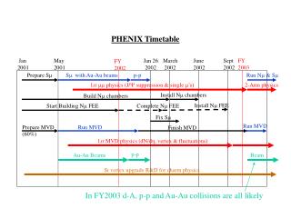
Status • Testboard in hand, populated, communication established. • LabView GUI essentially finished. • Testboard FPGA programming underway (estimate couple of weeks). • Miljko goes on vacation for 1 month shortly, Vince to BNL (MuID) for 1 month shortly. • Hope to test compatibility w/ pseudo-PHENIX DAQ in August. • Test w/ sensor in September?