Download
1 / 15
150 likes | 514 Vues
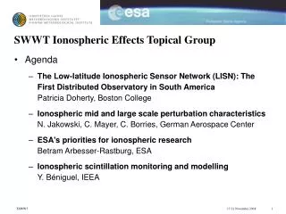
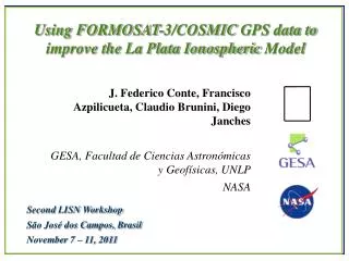
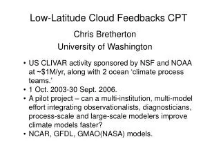
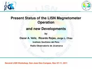
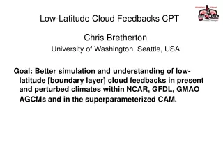
Low-latitude Ionospheric Sensor Network (LISN). C. E. Valladares, Boston College V. Eccles, Space Environment Corporation E. Kudeki, University of Illinois R. F. Woodman, Instituto Geofisico del Peru J. W. Wright, University of Colorado. Caracas, November 18, 2005. Project Goals.

E N D
Low-latitude Ionospheric Sensor Network (LISN) C. E. Valladares, Boston College V. Eccles, Space Environment Corporation E. Kudeki,University of Illinois R. F. Woodman, Instituto Geofisico del Peru J. W. Wright,University of Colorado Caracas, November 18, 2005
Project Goals • To build and operate the first Distributed Observatory across the western half of South America to study the low-latitude ionosphere. • To deploy many small instruments in a region bounded to the north, west and south by the continental boundaries and to the east by the 55° W meridian. • To transmit real-time measurements to a server that will assimilate the observable parameters and calculate geophysical quantities. • The instruments to be deployed are: 49 GPS receivers, 5 dynasondes and 5 magnetometers.
Scientific Tasks • To develop tools to forecast the initiation of the equatorial spread-F (ESF) phenomenon in a regional basis. • To study the electrodynamics of the low-latitude ionosphere during magnetic quiet and disturbed conditions. The distributed observatory will be able to measure the conductivity along a flux tube tell us how unstable is a flux tube to the initiation of ESF. It will measurement E region (100 km) densities at both feet of an unstable field line known to stabilize flux tube.
Fundamental principle of the dynasonde Pulsed radio waves of up to ~ 20 MHz (15m wavelength) may be totally reflected in the ionosphere, giving strong echoes even with rather low transmitted power (1 kW).
ESF echoes, GPS scintillations and TEC depletions A westward tilted plume reached 1400 km before 2100 LT. This altitude maps to the F region at 9° N.
UHF Scintillations & Frequency Spread F observed on Jan 27, 2003 TEC values Universal Time 0200 0300 0400
Real-time data flows of LISN data and assimilation results Real-time link (1) Low-latitude Ionospheric model, (2) low-latitude electrodynamics model, (3) model of ground-based magnetic perturbations for a 3-D current system (4) Kalman filter program. Real-time link
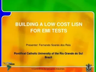
GPS receiver to be selected LEICA 1200 PRO TRIMBLE NetRS
Scientific and Technological Impact • We offer a plan to forecast Space Weather (ESF in particular). • Provide ionospheric corrections to WAAS-type systems. There is a need for real-time specification of ionospheric density. • Applications to Earth Sciences and Geodesy. • GPS Meteorology.
BC can provide the following equipment • GPS receiver and PC (laptop or Portable) • Local server • Solar panel, battery or a long-term UPS • Internet connectivity (DSL) • Cover some deployment expenses