Download
1 / 14
140 likes | 308 Vues
INSTANTANEOUS IN-SITU IMAGING OF SLURRY FILM THICKNESS DURING CMP. Caprice Gray, Daniel Apone, Chris Rogers, Vincent P. Manno, Chris Barns, Mansour Moinpour, Sriram Anjur, Ara Philipossian. Motivation.

E N D
INSTANTANEOUS IN-SITU IMAGING OFSLURRY FILM THICKNESS DURING CMP Caprice Gray, Daniel Apone, Chris Rogers, Vincent P. Manno, Chris Barns, Mansour Moinpour, Sriram Anjur, Ara Philipossian
Motivation • Microelectronic devices continue to decrease in size; current features are routinely smaller than 100nm • The semiconductor industry requires a deeper understanding of the physical processes involved in CMP to help attain smoother surfaces • Using Dual Emission Laser Induced Fluorescence (DELIF) we can measure instantaneous fluid film thicknesses (and temperatures) during a polishing run • Here we look at how the pad conforms to features on a wafer
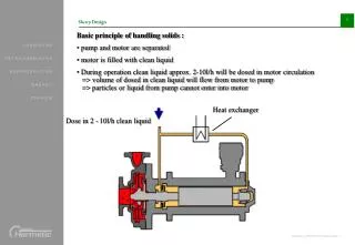
Polishing Setup • Struers RotoPol-31 table top polisher • Polisher sits atop a force transducer table capable of measuring down and shear forces during a polish
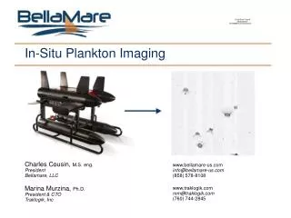
Optical Setup • Evolution VF 12 bit digital cameras • Region of Interrogation: 2mm by 3mm on the pad • 355 nm Nd-YAG Laser provides excitation light • Laser Pulse Length: 6ns
Dual Emission Laser Induced Fluorescence • Calcein, Coumarin in slurry solution • UV light excites Coumarin • Coumarin emission excites Calcein • Each emission is captured by a camera • Taking the ratio of the two emissions normalizes the image by initial excitation intensity • Images taken are 3 second temporal averages • Note: pads must be dyed black to mute any fluorescence
DELIF with One Dye • Natural pad fluorescence replaces Coumarin; Laser replaces UV lamps • Allows for non dyed pads • Laser now excites pad • Pad emission then excites Calcein in slurry • Since Laser is much more powerful than UV lamps, we can now take instantaneous images, not 3 second averages as before.
Experimental Parameters • Freudenberg FX9 Pad • Wafer & Platen Rotation: 30 rpm • Relative Velocity: 0.34 m/s • Downforce: 1.8 PSI • Slurry • Flow Rate: 50 cc/min • 9:1 dilution • 0.5 g/L Calcein
Previous Work • Film thickness increases as pad speed increases • Inverse relationship for downforce and thickness • Film thickness are measured from the wafer surface down to some mean height within the pad
(b) (a) Calibration • These known heights allow for a calibration of intensity to fluid film thickness • The 27 micron deep well (b) is brighter than the 14 micron deep well (a), indicating more fluid 2mm
Results • Surface roughness calculations compare single points in an image to a mean thickness value • Indicates the wafer is compressing the pad • Roughness of: • Red square = 3.40.3 • Blue square = 4.20.3mm • FX9 Pad (from profilometer) = 4.30.3mm
(b) (a) Results • 22% of images of the 27 micron deep well show air bubbles • The roughness in the air bubble is between the roughness inside and outside of the well
Results • Previous modeling research has shown that pressure varies locally beneath a wafer suggesting that we must interrogate many other regions before we can draw any significant conclusion about roughness variation with applied global down force.
Conclusion • This work supports the notion that the CMP polishing regime is in the partial lubrication regime • Wafer is partly supported by asperities, partly by fluid pressure • If it were true hydrodynamic lubrication, the roughness under the wells would be the same as the rest of the pad • The asperities are free to expand under the etched wells and do so
Future Work • Investigate larger region/multiple regions under the wafer • Correlate downforce with surface roughness • Refine calibration method to determine absolute thickness • Roughness reported here is a relative measurement