Download
1 / 48
480 likes | 514 Vues
Looking for Gravitational Waves with LIGO. Michael E. Zucker LIGO Laboratory, MIT Brookhaven National Laboratory December 5, 2002. DESIGN CONSTRUCTION OPERATION. SCIENCE. Detector R&D. LIGO Laboratory MIT + Caltech ~100 people Director: Barry Barish. LIGO Science Collaboration

E N D
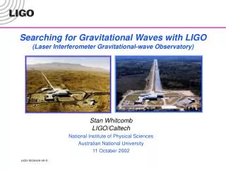
Looking for Gravitational Waves with LIGO Michael E. Zucker LIGO Laboratory, MIT Brookhaven National Laboratory December 5, 2002
DESIGN CONSTRUCTION OPERATION SCIENCE Detector R&D LIGO Laboratory MIT + Caltech ~100 people Director: Barry Barish LIGO Science Collaboration 44 member institutions > 400 individuals Spokesperson: Rai Weiss UK Germany Japan Russia India Spain Australia $ U.S. National Science Foundation LIGO Organization & Support
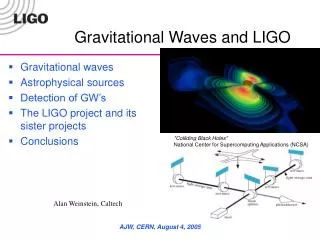
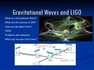
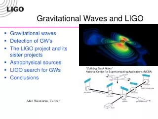
Gravitational Waves Classical ‘action at a distance’ is prohibited. Gravitational perturbations must then propagate at c like other information. K. Thorne (Caltech) , T. Carnahan (NASA GSFC)
Evidence Energy loss from binary pulsar (Taylor and Hulse, ‘81ff) clearly due to gravitational radiation. Our problem: to detect and use them to study physics of sources and spacetime
Effects • Assume small perturbations hon a smooth metric • Einstein equation yields a wave equation, velocity c, for perturbations • Local geodesics in path of wave stretch in one transverse dimension while compressing the orthogonal • Since gravity is spin 2 tensor field, two independent polarizations rotated by/ 4 • Since there’s no mass dipole, lowest order radiation is quadrupole • Strainh observable as fractional change in geodesic length
Interferometer Detectors • Michelson-type interferometer compares orthogonal geodesics • Concept proposed as early as ‘52 • Weiss (‘72) made first serious analysis; main features and limits identified still apply, although technology greatly advanced • PROBLEM: waves are weak, e.g., for ns inspiral we estimate i.e. for km-scale receiver, L ~ 10-18 m Compare: that's ~ 10-12 laser , 10-8 Å , 10-3 fm Kinetic energy imparted to 10 kg test body in 10 ms E~ 10-9 kT OK, THIS IS A HARD EXPERIMENT ... WHAT'S THE PAYOFF?
Pre-20th Century (Visible) Universe http://antwrp.gsfc.nasa.gov/apod/ap010202.html
New Instruments,New Universe • Janksy, 1933: antenna built to diagnose transatlantic telecommunications interference accidentally discovers radio emissions from the galactic center • Revolution: totally different objects & underlying principles • Entire history of astronomy turned out to be a myopic selection: looking under the lamppost http://www.lucent.com/museum/1933rt.html //http://rsd-www.nrl.navy.mil/7213/lazio/GC/
Infrared Sky (COBE DIRBE) http://antwrp.gsfc.nasa.gov/apod/ap980128.html
X-ray Sky (ROSAT multi-energy) http://antwrp.gsfc.nasa.gov/apod/ap961008.html
Gamma-Ray Bursts (BATSE) http://www.batse.com/
Speculations: The Gravitational View Complementary as these views are, all depend on EM waves from object surfaces, gases & plasma; and all are strongly scattered and/or obscured GW's emanate from bulk accelerations of dense cores, pass unimpeded through intervening matter Neutron stars, quasars, black holes, GRB's, etc. were never anticipated; what might the "brightest" GW sources be? Inference: EM-observed phenomena with known or implied
gravitational waves emitted Nonaxisymmetric supernova (milliseconds) (seconds) computed strain waveform (hours) Zwerger & Mueller, Astron. Astrophys. 320, 209 (1997) Dimmelmeier, Font & Mueller, Astrophys.J. 560 (2001) L163-L166
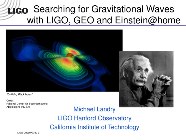
Example: BH/BH Mergers Explore Dynamic Spacetime Warpage GW’s expose dynamic object cores, not just luminous surfaces; describe total mass, not specific species, reactions or temperatures GW’s pass unabated through intervening matter Most prominent sources may well turn out to be unpredicted from what is known by other methods!
Earth orbital diurnal frequency frequency time time Periodic ("CW") Signals • Many fast radio pulsars now known with rotation rates (x2) in LIGO frequency band • Eccentricity 10-4 < e < 10-6 possible from • oblateness x axis wobble • accretion-driven surface waves • GW-driven body waves • Signal always "on", coherent integration continually improves SNR • Doppler shift from Earth and/or source motion requires specific phase ephemeris • Unbiased all-sky all-frequency search computationally "interesting" Jodrell Bank Observatory
Stochastic GW Background from the Early Universe • GWs probe the earliest universe; "transparency" at the Planck time • Constraints from other physics imply GW background weak, but more pronounced mechanisms proposed (primordial strings?) Cosmic microwave background ? Allen & Romano, gr-qc/9710117 Maggiore, gr-qc/9909001
LISA Three drag-free satellites flying in formation, linked by laser beams Joint ESA-NASA program Launch planned for 2010 5•106 km separation (10-4 - 10-2 Hz)
LIGO Observatory Sites Hanford Observatory • Coincidence • local environments uncorrelated • Amplitude discrimination • half- and full-length IFO's share Hanford site • 1:2 ratio required for true signals • Source triangulation* • ± 10 ms time of flight • ~ arcminute directionality • Source polarization* Livingston Observatory *weak, need other worldwide sites!
GEO Virgo GEO TAMA LIGO TAMA VIRGO LIGO Hanford LIGO Livingston AIGO* International Interferometer Network • Detection confidence • Source polarization • Sky location *planned
Seismic Noise Quantum Noise Residual gas scattering Radiation pressure "Shot" noise Wavelength & amplitude fluctuations Thermal (Brownian) Noise LIGO Interferometer Noise Limits test mass (mirror) LASER beamsplitter photodiode
Interferometers: noise background • Initial sensitivity limits • seismic noiseat the lowest frequencies • thermal noiseat intermediate frequencies • shot noiseat high frequencies • Based on conservative extrapolation of prototype technologies (circa ~'97) • Facility limits designed much lower to allow improvement as detector technology advances detectable signal zone
Want "optical" arm length ~ GW /4 for best antenna response • Adds complexity; now each arm needs to be held near • L = k * LASER /2 • Add mirror to "recycle" photons (equivalent to more laser power) 4 km Fabry-Perot cavity recycling mirror 150 W LASER 3000 W 6W (0.2W) LIGO Interferometer end test mass
LIGO Observatory Facilities LIGO Hanford Observatory [LHO] 26 km north of Richland, WA DOE Hanford Nuclear Reservation 2 km + 4 km interferometers in same vacuum envelope LIGO Livingston Observatory [LLO] 42 km east of Baton Rouge, LA LSU fiducial owner of site Single 4 km interferometer
Beam Tubes and Enclosures • Beam Tube • 1.2m diam; 3 mm stainless • special low-hydrogen steel process • 65 ft spiral weld sections • 50 km of weld (NO LEAKS!) • 20,000 m3 @ 10-8 torr; earth’s largest high vacuum system Precast concrete enclosure: bulletproof
Vibration Isolation Systems • Reduce in-band seismic motion by 4 - 6 orders of magnitude • Large range actuation for initial alignment and drift compensation • Quiet actuation to correct for Earth tides and microseism at 0.15 Hz during observation
Seismic Isolation System Tubular coil springs with internal constrained-layer damping, layered with reaction masses Isolation stack in chamber
Core Optic Metrology • Current state of the art: 0.2 nm repeatability LIGO data (1.2 nm rms) CSIRO data (1.1 nm rms) • Best mirrors are /6000 over the central 8 cm diameter
Feedback Control Systems • Array of sensors detects mirror separations, angles • Signal processing derives stabilizing forces for each mirror, filters noise • 5 main length loops shown; total ~ 25 degrees of freedom • Operating points held to about 0.001 Å, .01 µradRMS • Typ. loop bandwidths from ~ few Hz (angles) to > 10 kHz (laser wavelength) example: cavity length sensing & control topology
S1 LLO 4k Noise Analysis @ S1 Data Run (8/02) R. Adhikari, http://alix.ligo-la.caltech.edu/ilog/
Estimated noise for S2 (2/03) after current mod's. R. Adhikari, http://alix.ligo-la.caltech.edu/ilog/
noise signal Data Analysis Overview (transient signals) Event Triggers Strain readout Candidate events LDAS Diagnostic & environmental monitors Veto Triggers DMT Coincident Events IFO 2 Search Algorithms IFO 3 sum
Optimal (Wiener) Filtering • Classical method from early days of radar (known signal) • Convolve ensemble of expected signal waveforms (templates) with detector output, weighted by inverse of noise background • Templates "meshed" to minimize redundancy w/out holes • Output SNR maximized in best-fit template at time of signal; detection PLUS source parameter estimation at once • Well-suited to parallel processing in cluster of computers Parallel PC Linux Cluster
Chirp SignalBinary inspiral chirp at high SNR parameters: • Distance from the earth r • Masses Miof the two bodies • Orbital eccentricity e and inclination i • Waveforms calculable to adequate accuracy for detection • Need O(105) templates to cover 1-10 solar mass range
time Ringdowns Stochastic Background frequency Bursts CW (quasi-periodic) Chirps Time-Frequency Representation of Possible Signals • Bursts: • Short duration, broadband • supernova, disruption/merger ? • Chirps: • long-term coherent • BH/ns coalescence • BH ringdowns: • damped ringing of event horizon after merger/capture • CW sources: • Doppler FM depends on sky position, source motion • pulsars • Stochastic background • stationary broadband noise Suggests robust "pattern" methods, possibly less dependent on exact prediction
Freq. time t-f Clustering Algorithm • Way to look for unmodeled, poorly parametrized or "incoherent" (e.g., chaotic) bursts • Can apply physics cuts on size, shape of clusters without specific waveform knowledge • False alarm rates predictable, given noise properties • Detection efficiency hard to estimate; rely on Monte-Carlo • so to place a flux limit, in the end you do have to specify a signal form Threshold pixels on normalized power Find "clusters" & re-threshold on total energy Generate spectrogram J. Sylvestre, LIGO-P020010-00-D
STATUS • Construction is finished! Detectors work! • Completed S1 science data run August '02 • 96 h "triple coincidence," TAMA (Japan) and GEO (Europe) also on air • Data analysis in progress; expect to set GW flux upper limits significantly more stringent than previous searches • Preprints coming out in January • Upgrades to detector electronics, alignment systems, software after S1 should give about 5x better sensitivity and improved duty cycle • 8-week S2 science run planned for February-March • Improve & refine flux upper limits & detection algorithms • Major upgrade to seismic isolation, other systems planned after S2 • S3 science run (~ 6 months) to begin late 2003 • Beginning of serious search for astrophysical signatures
Present and future limits to sensitivity • Facility limits • Gravity gradients • Residual gas • (scattered light) • Leaves lots of room for improvement • Advanced LIGO • Seismic noise 4010 Hz • Thermal noise 1/15 • Shot noise 1/10, tunable • Beyond Adv LIGO • Thermal noise: cooling of test masses • Quantum noise: quantum non-demolition
Advanced Interferometer Concept • Signal recycling • 180-watt laser • Sapphire test masses • Quadruple suspensions • Active seismic isolation • Active thermal correction
Active Seismic Isolation • 2-stage internal active stack w/blade springs & flexures • 6 degrees of freedom each stage • Sensors encapsulated in airtight ‘pods’ • Magnetic voice coil forcers • Digital MIMO control system Prototype 2-stage active isolator developed at MIT • External active pre-isolator • Shields quiet internal system from most seismic energy • Hydraulic & magnetic variants under study • Program accelerated for early retrofit to initial LIGO interferometers
Advanced Suspensions • Based on successful GEO triple pendulum design • Quad pendula for TM, BS; Triples for input optics • Blade springs for vertical isolation • Indirect damping through upper stage recoil • Electrostatic or photon drive for fast control at final stage; reaction mass for ES recoil R. Jones, Glasgow U.
Advanced LIGO Reach • R&D since '98 • Proposal now in preparation • Goals: • Quantum-noise-limited interferometer • Factor of ~ ten increase in strain sensitivity => ~ 1,000 x increase in event rates • Schedule: • Begin installation: 2006-7 • Begin observing: 2007-8 Science from the first 3 hours of Advanced LIGO observing should be comparable to 1 year of initial LIGO
Concluding Remarks • LIGO and other worldwide gravitational wave instruments are on the air and rapidly approaching design sensitivity. • While we study the initial data, we're planning more powerful instruments to follow. • Each new observational window opened in the last century revealed amazing and unexpected secrets; the gravitational wave window is about to open. WHAT WILL WE SEE?